Titanic Trumpeter 1/200 by InkMot

Joined
Dec 26, 2021
Messages
22
Points
48

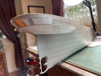
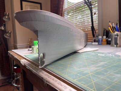
This is a log of my progress with the Trumpeter Titanic. I know that there are many of these and I appreciate your patience with my contribution. My hope is to share the things I’m learning about the kit along the way, including my experiences with the third-party detail kits. Every project should have a goal. My goal for this build is to create an accurate impression of the ship as she departed on her maiden voyage. I define accurate as that which would seem obvious to an observer who’s familiar with the ship from about 2 feet (.6 meters) away, avoiding the addition of such things as photo-etched brass when I feel its inclusion would actually detract from realism, e.g. I’ll show you why I swapped out the Minibrass stern plating in favor of .13mm styrene. I’m not sure I’ll want the model to be lit up, which may also mean that I won’t spend too much time on interior spaces. I’ll wait to see what is observable from 2 feet away. I’m not building a dollhouse.

Thanks for your interest so far.
IMG_6052.jpeg
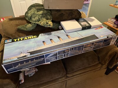
This is what I began with: A Christmas gift from my wife in December 2021. It went on the shelf while I completed a 1/80 scale, launch-able Saturn V rocket kit - which I’m now too afraid to launch. ;-)
 
I was able to begin the kit late last year. Phase 1 of the Trumpeter Titanic kit is working on the hull. Major tasks include: (Items in bold have been completed)

1. Cleaning up the mold marks on the bottom, much sanding is involved here. Leaving a indication of the seam line is useful, if you plan to plate the bottom of the hull later.

2. Adding plating detail to the stern. The kit lacks detail here due to the limits of mold-making. You’ll want to consider what to do about including plating. I started with the MiniBrass stern plating and switched later to styrene.

3. Correcting the plating at the rudder post and center screw area.

4. Adding condenser ports mid-way up the hull on either side.

5. Plating the bottom of the hull: The kit is completely smooth on the bottom. This bothered me. Perhaps it shouldn’t have.

6. Correcting the hawse pipe at the bow. This is major work that involved installing a 3d-printed hawse pipe and re-plating. What is wrong with me?

7. Correcting and installing the propeller wave wings: This involves correcting the plating and thickness and blending to hull.

8. Correcting and installing bilge keels: I ordered 3d-printed replacement keels. In retrospect, I could’ve just made them from sheet styrene.

9. Correcting portholes, plating and thickness at B and C Deck: I’m going with the MiniBrass hull plating kit here. It’s on order. It involves cutting and drilling much of the hull sides and a great deal of blending with the rest of the hull. I imagine that’s how I’ll be spending the winter.

10. Drilling portholes: I’m not committed to lighting the ship, but I’ll likely insert something to show porthole glass, which will require actual holes.

11. Scribing Ship Name: I’m going back and forth between the MiniBrass ship name plates and just scribing the name in the hull. We’ll see how crazy I get.

12. Final install of brass details: Hull doors, pad eyes on stern, porthole bars, etc. Basically, anything that could get damaged if I install them too early in the build.

13. Masking and Painting: This will involve final hull prep, measuring and marking waterline and painting. My plan is to use an airbrush, not matter how long this will take, so that I can keep the paint layers thin.
 
Adding Plating Detail to Stern:

The original kit offers a pretty plain stern, which seemed to stick out to me with such a large model.
IMG_0222.jpeg
Here’s a picture I found online of the stern as it looks out of the box. As you can see, it’s missing a lot of details. I’ve read that his is due to the molding process that makes it impossible to include details on what would be a horizontal plane of the mold.

There are several options to add your own plate details: 1. Scribe in plates, 2. Purchase and install an after-market kit or 3. Make your own plates. I’ve seen at least two plating kits available, the MiniBrass brass plated stern kit and there are styrene plate kits (I learned about this after I made mine. Here is a link to a kit that The Midwest Model Shop sells for $45: https://www.themidwestmodelshop.com/store-1/p/titanic-styrene-stern-plate-set) The MidWest Model Shop YouTube channel also has a video on making your own plates using a Cricket craft cutter here:

I initially went with the MiniBrass plate kit and abandoned it later (I’ll explain.). There is an excellent tutorial on this from John Builds Iconic Military Models:

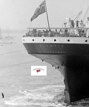
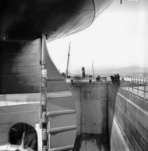
Why I abandoned the brass plating: My goal was to add the plating detail to the stern and to make it look as close as possible to this photograph:
IMG_0124.jpeg
Note that you can see the hull plating on the Olympic above, but that it’s pretty flush and smooth. I discovered that I couldn’t achieve that with the MiniBrass plating. This wasn’t because the brass plates are too thick, they’re just about the equivalent of 1” thick at 1/200 scale, it was largely due to the layers of CA glue that accumulate between plating. What I ended up with was plating that was sticking out from the hull too far. It was about 1 foot out if it were at 1/200 scale. To me, this is an example of a detail detracting from the realism of the project. It would be better to have no plating. I removed all of the brass and used each plate as a template for cutting out new plating from .13mm styrene. I also used the MiniBrass template to help me lay out the plating, etc.

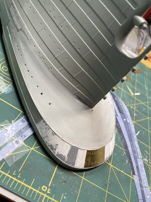
No matter which direction you choose, you’ll need to sand the stern area to make it flush for your new plating. I also chose to carve out the plating on the side of the hull to enable the new plating to lie flush with the molded plating.IMG_0580.jpeg
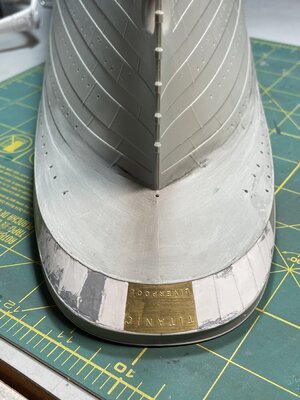
Here’s a shot of the stern of my project, showing the area that I sanded smooth for plating. This is a bit later in the work, after I’ve removed the MiniBrass plating. You can also see that I’ve plated the upper stern with styrene and left the MiniBrass nameplate (The MiniBrass kit offers a choice of nameplates. You can choose raised or recessed lettering. I mistakenly chose raised and decided to leave it in place. The Titanic had recessed or etched lettering on the hull.)
IMG_0923.jpeg
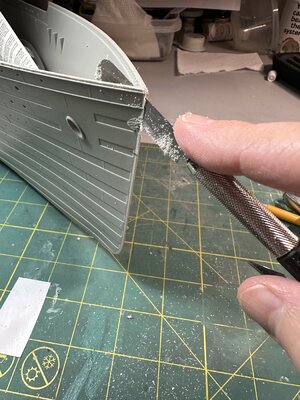
You can see the area forward of the stern where I’ve carved out the area for the new plating to be inserted. I did this with the X-acto chisel blades and the regular blades. Just take your time and scrape away.

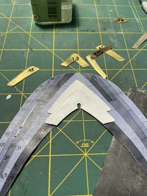
The MiniBrass kit comes with a template for laying the new plates. This came in handy for marking out the areas to be sanded and carved. The template is also used for showing the sequence and location for plates. Here I’ve begun laying out my styrene plating using the template. Note how I’ve numbered each MiniBrass plate to keep track. If you’re using the brass, the recommendation is to work the plating in sections. You can chose to do the entire plating work on the template, using styrene.
.IMG_0728.jpeg
Another advantage of styrene was that I was able to work with Tamaya Extra Thin Cement. This stuff is glorious. It secures promptly but allows time to adjust the plating. Make sure that you use extremely thin coats if you’re working with .13mm styrene. The putty areas you see on the upper stern plating were to repair distorted plastic from the glue.

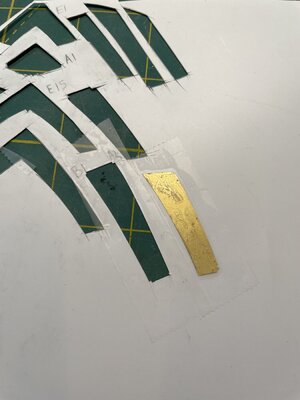
Here’s the process for cutting out the plating from plastic using the MiniBrass plates as templates:
IMG_0813.jpeg
I taped the plates to the plastic, following the layout pattern of the brass kit (laid out approximately how they’d attach to the hull) to keep things organized. I obsessively labeled everything to stay sane. The metal plates made it easy to cut the plastic with an x-acto knife. I carefully sanded each piece to remove the ridge created by the cutting process. I wanted my plates to lay as flush as possible on the hull.
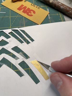
IMG_0814.jpeg

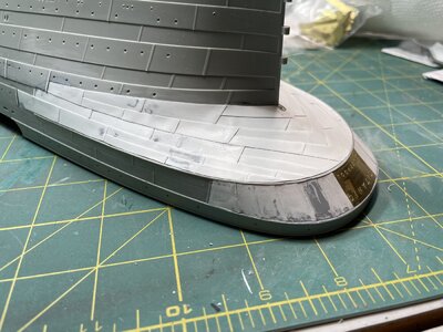
Once I completed the entire stern plating on the paper template, I transferred the entire structure to the stern, gluing from the center of the stern forward on each side. I trimmed around the edges to ensure that the plates were flush with the rub rail. I went back through each plate to ensure that it was secured to the hull and to adjoining plates. Tamaya’s Extra-Thin cement was a huge help here, since it flows right into gaps. I also filled in gaps with putty and finished with a primer layer. I’ve since sanded and re-filled several times, whenever I’ve detected a gap or defect.
IMG_0964.jpeg
All of the plates are in place. It’s not perfect, but it’s closer to the hull and seems to blend well with the molded plating.
IMG_0930.jpeg

IMG_0932.jpeg

IMG_0963.jpegIMG_0966.jpeg
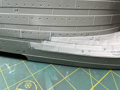
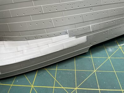
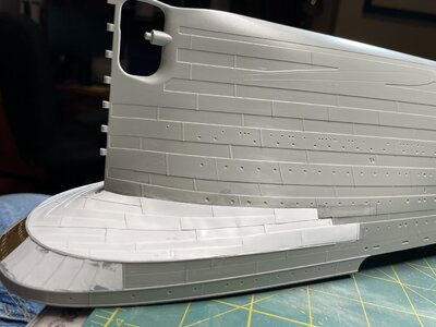
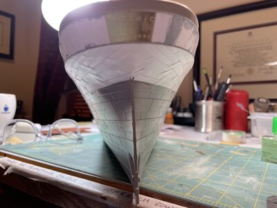
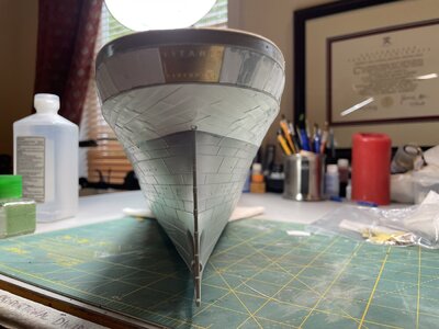
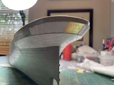
Here is where the etching or carving of the hull helped me to blend my new plating with the hull. I’ve also added vertical strips to replicate where the plates lap each other. Note the endless filling of damaged plates surfaces from glue or other mistakes.
IMG_0968.jpegIMG_0969.jpegIMG_0970.jpeg
IMG_0972.jpegIMG_0124.jpeg
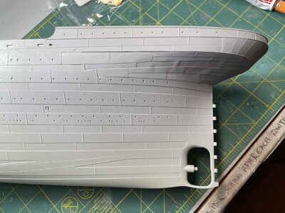
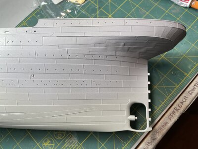
Here’s the stern area with an initial coat of primer. I’ve since sanded this and did some more filling. I think I got close to the original. Note that the blocks for servicing the propellers (screws) that you see on the photo of the Olympic will be added just before I’m ready to paint. I will also drill out the portholes on the stern later.
IMG_0974.jpeg
I’ll keep working to minimize the wavy areas of the plating. This is due to how thin the plates are. I don’t think it can be helped. Thicker plates are smother, but they stick out more. Pick your poison. I am satisfied with the way that the new plates blend.
 
Last edited:
Correcting the Plating at the Rudder Post:

IMG_1835.jpeg
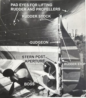
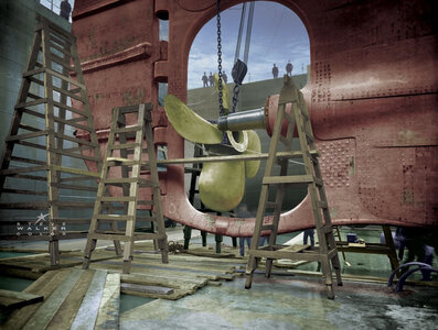
The Olympic in dry dock (photo from Titanic, The Ship Magnificent), showing how the hull plates lay on top of the stern frame, revealing the after half of the frame where the gudgeons attach. Note also how the center propeller boss is faired.

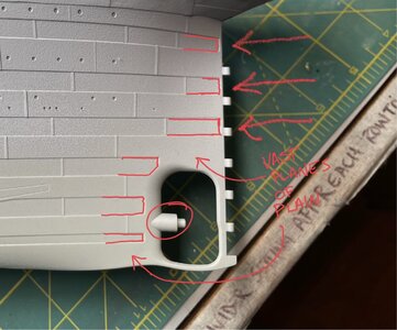
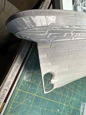
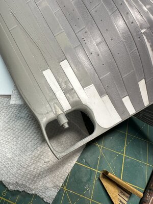
The fun at the stern keeps going! If you look at the plating along the rudder post and compare it to a photo of the Olympic (see above), you’ll see that there are opportunities to excel. The molded plating end at a vertical “plate” that was molded into the kit. This plate doesn’t exist on the actual ships. The plates on the actual ship end at the rudder post and lay on top of it on an in and out pattern. There are also “vast planes of plain” above the center propeller opening and just forward of it ear the keel. To correct this, I had to add plating and scrape away the vertical molded plate. I wanted it to look like the plates were attached to the stern frame and I wanted to reveal the after portion of the stern frame.

IMG_0974.jpeg

One of the first things I did was to break out the x-acto with the chisel blade and start shaving the plastic that makes up the mythical vertical plate at the rudder post, etc. I think this molded post was meant to indicate the lip of the rudder post, aft of the end of the hull plates. To replicate this, I also planned to add plating over the inner plates on the hull, so that I could show a plate terminating on the stern or rudder post.
IMG_0860.jpeg
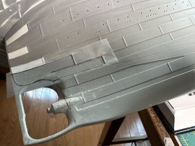
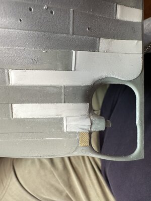
This picture shows where I’ve scraped out the inner plates and I’ve also removed the molded gudgeons, since I’m replacing the kit’s rudder with a 3d-printed one that has it’s own very accurate gudgeons. You can also see where I’ve added the epoxy putty to form the base of the fairing on the center propeller boss.

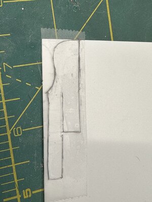
Once I carved out all of the areas where I planned to add plating, I began to measure and cut new plates. The trick I used (I saw this somewhere. I’ll add a link when I find it.) was to use clear tape to create a template. I placed the tape over the plate opening I carved and traced it with a thin Sharpie. I then transferred the tape to the styrene sheet and cut it out using an x-acto. All plates were carefully sanded and shaped before being cemented in place with Tamaya Extra-Thin cement. I used a water-based filler to close the gaps with the hull.
IMG_0864.jpeg
Example of using tape as a template for cutting plates. Note the tracing around the edge of the carved area.

IMG_0865.jpeg
The template was then placed on the styrene sheet for cutting.

IMG_0870.jpeg
This picture shows much of the plating installed. Note the plates creating the center propeller bus fairing and the vertical strips to replicate the areas where the plates overlap.


The kit does not replicate the fairing around the center propeller shaft. It just molds it as a straight cylinder. I built up the area just forward of the propeller shaft using epoxy putty. I then plated over it with .13mm styrene. (See photo above as well.)
IMG_0346.jpeg
The epoxy base for the propeller boss fairing.
IMG_0875.jpeg
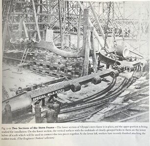
The Olympic in dry dock showing the lower portion of her stern frame and the plating around the center propeller boss and below, near the keel. Note also the grid of rivets just below the center propeller boss. This is an attachment point for the stern frame.

IMG_1834.jpeg
This photo from “Titanic, The Ship Magnificent” shows where the stern frame attaches below the propeller boss (white box area with holes).

I added a brass detail part that replicates the riveted area below the propeller boss. The trick was that this isn’t supposed to be a plate that sits on the surface, it represents the rivet heads that attach the stern frame. So I had to carve out a square area and inset the plate, then putty the seams.
IMG_1136.jpeg
The brass plate, simulating the riveted area is in place and filled in with putty. Note the “rivet rows” on the end of the plating and the carving to simulate the ends of the hull plates at the stern frame. The plating from the Maritime Models Under Hull Plating kit can also be seen. I’m holding the 3d-printed replacement rudder in place.

The lowest part of the stern requires plating as well, but I used the Maritime Models RMS Titanic Under Hull Plating Kit for this. This kit is a big project and I’ll cover it in another post. But you can see where the bottom plating meets the side plating area in the photo above.
 
Last edited:
The work you are doing on your 1/200 Titanic is excellent.
I have the same model, but have put it away for the time being.
I bought all the Woody's Models interior for mine (not sure if that was a good idea).
I have replaced the hawse pipe in the bow with the 3d printed one from Shape ways.
It’s a very tricky job to get correct when fairing into the hull.

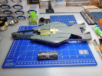
Presently I am working on the 1/48 F14D Tomcat from AMK models, I have cut away most of the panels in the fuselage and at the back of the model to show the resin jet engine. the spine along the top of the model has been removed to expose all the pipe work.
I also bought the the resin landing gear and open exhause nozzles from Res Kit.20230111_223810.jpg

Each of these models have their challenges.

Enjoy your weekend.
Beau.IMG_20231125_132044.jpg
 
The work you are doing on your 1/200 Titanic is excellent.
I have the same model, but have put it away for the time being.
I bought all the Woody's Models interior for mine (not sure if that was a good idea).
I have replaced the hawse pipe in the bow with the 3d printed one from Shape ways.
It’s a very tricky job to get correct when fairing into the hull.

Presently I am working on the 1/48 F14D Tomcat from AMK models, I have cut away most of the panels in the fuselage and at the back of the model to show the resin jet engine. the spine along the top of the model has been removed to expose all the pipe work.
I also bought the the resin landing gear and open exhause nozzles from Res Kit.View attachment 409358

Each of these models have their challenges.

Enjoy your weekend.
Beau.View attachment 409359
The hawse pipe replacement is quite a project. I recently completed that (Well, I could always do a bit more. ;-) ) and I’ll post photos soon. Yours came out great! The one I purchased from shapeways included the fairleads on the top of the bow, so it was fun getting all of that aligned and filled in. Here’s the shapeways part: https://www.shapeways.com/product/P...mail&utm_campaign=order-shipped&utm_content=7

I’m interested to see how the F-14 progresses. Will you be sharing that online somewhere? It will be interesting to see how you display it. I work with a former F-14 RIO (think “Goose” from Top Gun). You can’t convince him that the F-14 wasn’t the best fighter ever made. ;-)
 
Great progress,Beau! Looking foreward to see more as you do a lot of effort put into your job! It is great to look onto your progress and invest into looking for propper sources.

I editly added some lines in here:
So I am awaiting a lot of interesting detailing into and onto this big kit.

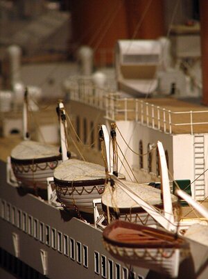
An unteresting detail I found by the way you may find helpfull due to famous

Lifeboat N° 1
Titanic_model_lifeboats.jpg

Have you made a list of your changings/additions to your kit? Or do you take a look on a kit part and think about the way of "pimping" it spontaniously?

Best wishes from Berlin, Christian
 
Last edited:
What may help is to redo the plating aft:
IMG_0974.jpeg
Gluing them not overlapping but joining flat front to front alined and than an Evergreen quare plastic stick in the right measurement (like these on the kit's moulded joints) glued atop the joints - as you have already done it twice at the midstpropeller:
Polish_20231125_203641263.jpg

And it seems to be right compared to the original:
Screenshot_2023-11-25-20-47-10-893-edit_com.pinterest.jpg

To keep the plastic plates connected to the surface over the hole length strong minimagnets are a very helpfull and cheap possibility to do the job (I did use them for circular camouflage on late German WW2 tanks).

H.t.h.,C.
 
Last edited:
Thanks for the likes on my previous Trumpeter project.

The Titanic 1:200 is one of the worst kits from the Trumpeter series, poorly executed in my opinion.
I wouldlike to add lighting, but the lighting should be subtly illuminated where not all portholes are illuminated, and with lighting that is appropriate for that time.

I don't like a dollhouse either, but I will show the interior because I think this is an added value of the model, this with lighting will be a nice challenge for 1:200. I will post a report soon

now the rear plating with Evergreen and the hull sprayed with Vallejo Color

As usual, photos with your phone do not reflect the reality of the colors, but here is a photo
IMG_1961.jpg
Regards Henk
 
Hello Henk,
your dislike of a dollhouse is understandable. As I did plan to build
ddpmeo7-be962c29-7bc2-4b0a-a3e5-be29bbc5adf7.jpg
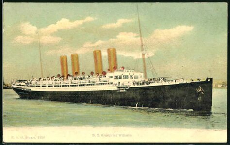
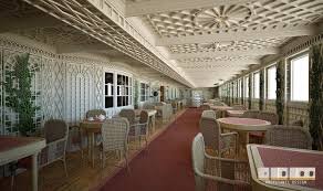
S.S. KRONPRINZ WILHELM* of 1901 by NDL in 1:100. I planed to glue boxes with coloured walls and interieur behind the big windows - as anything else looked like a sad emptyness to me (and this in particular as the gap between the mid funnels gave way for more day light into the dining room 1st class).
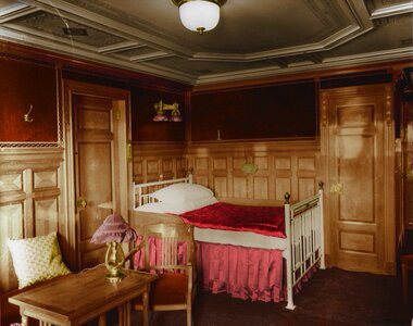
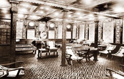
So colouring these unfolded boxes after the (ugly disgusting oversweeted & overkillsugraed) lovemovie with an astonishing ammount of detail into the model may be a good idea to figure out the right Colours in particular for the rooms with big windows on the boats deck...

download (1).jpeg
The CAFÉ PARISIEN will be a challenge in it's own right!

I decided to go for fivesided cubes - from thick paper and glueing them between two L-shaped bars following the deck's curve. So it was easy to paint the interieur in chamouse-yellow, sage-green &c. Than folding the four sides and putting it in place. Also an gangway entrance would be possible by this method . I also got imitated one staircases to be "seen" through an open door with an easter egg included:
20200106164200!NosferatuShadow.jpg

Fivesided cubes are easy to colour, copy, and adjust.
B57C1024.jpg
The Ottoman bath will Not be anything you could see from outside, wouldn't you?
Titanic-Turkish-baths.jpg

the-luxury-dining-hall-of-the-rms-titanic-news-photo-1643817406.jpg
The diningroom first class is also able to be build in abreviation as a lot of the social rooms.

The daylight by this isn't something you are affraid of, as there is something to imagine behind any opening (even those not enlighted) in any angle of view.

*btw the yellow of the funnels isn't bright enough as Arnold Kludas told me!!!
 
Last edited:
Condenser Discharge Ports:
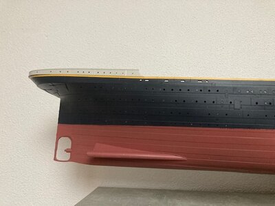
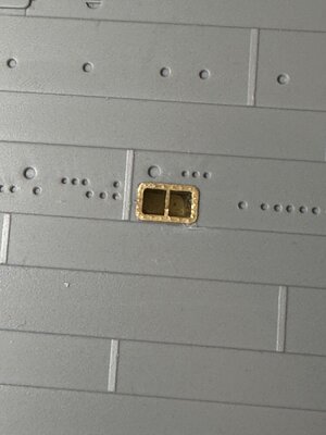
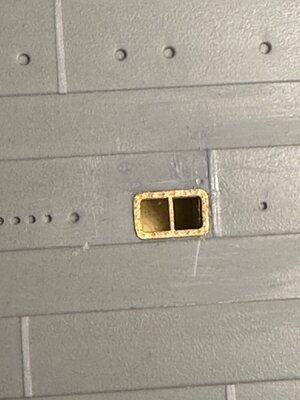
The kit is missing the condenser discharge ports on either side of the hull. I used the MiniBrass versions, but there are several other options, including some 3d-printed versions. Installing the MinBrass condenser discharge ports involves locating the right spot mid-hull at the waterline, drilling and shaping a rectangular hole, forming the inner box from brass pieces, shaping the hole to fit, securing with CA glue and then covering the opening with the condenser discharge port screen. In retrospect, I’d locate both of my ports about 1/4” further aft. They should be centered between the plate seam and the row of other discharge openings. Oh well.
IMG_0347.jpeg

IMG_0348.jpeg
IMG_0228.jpeg
 
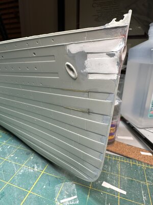
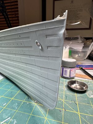
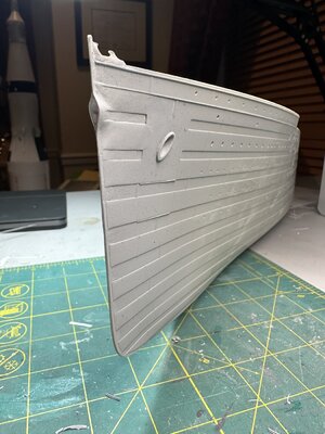
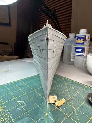
Correcting the Hawse Pipe at the Bow:

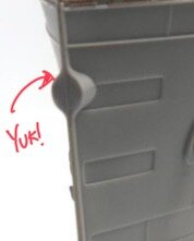
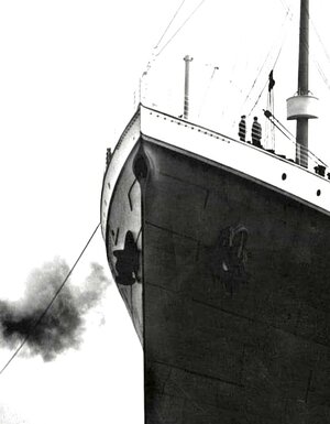
I felt that correcting the hawse pipe mattered. To me, it’s similar to not getting the mouth right when you’re painting a portrait: the viewer senses that something isn’t quite correct. The Trumpeter kit makes the hawse pipe opening too round and does not blend it gradually into the hull. It also lacks the plating detail that should be seen on each side.
IMG_0229.jpeg
This is the kit hawse pipe. Not ideal.

IMG_1652.jpeg
I wanted my hawse pipe to look more like this.


IMG_0204.jpeg
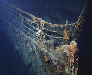
I also wanted to have the fairlead blocks and the right mounting point for the mast shroud, like you can see on the actual wreck.


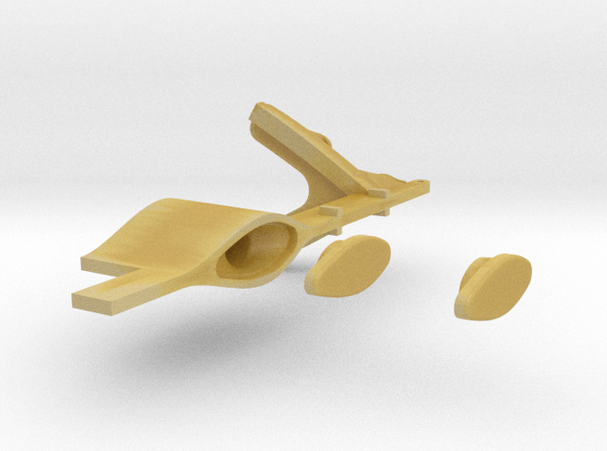
Correcting this involves purchasing a 3d-printed insert from the Shapeways site. There are many offered there. I went with this one:
I liked that this version included the fairlead blocks on the top of the bow. This is a prominent Titanic feature that also doesn’t appear in the kit.

IMG_1451.jpeg
The 3d-printed hawse pipe and fairlead blocks. Be careful with this. It’s brittle.

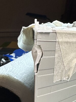
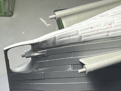
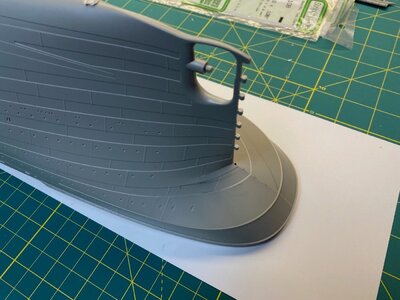
The first step was to saw a vertical cut from the bow peak down to just below the hawse pipe. The length was based on a precise measurement of the 3d-printed part. I used a digital caliper to measure and a Tamaya hand saw to cut. I used a Dremel tool to grind down the original hawse pipe on either side. You then need to cut out the area where kit-molded hawse pipe was and then enlarge the vertical opening just enough to accommodate the 3d-printed replacement. This was a great deal of trial and error over several working sessions. I cycled through test fitting the part and filing the openings. You need the top portion with the fairlead blocks to sit on the top of the bow while the hawse pipe opening ends of oriented correctly and in the right location. There’s a portion of the bow, above the rub rail that must be removed for the fairlead blocks to sit correctly. I also had to add a few strips of styrene to fill in the gap below and to build the rub rail back up. A better surgeon might not have to do this.
IMG_1452.jpeg
The initial cut. No turning back now! (Note the ground down original hawse pipe)

IMG_1540.jpeg
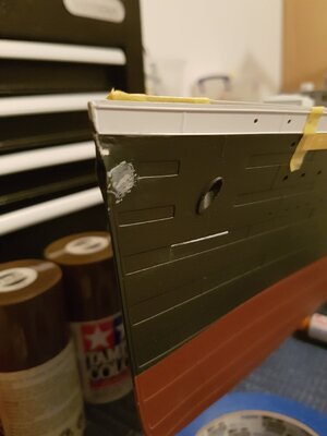
View of the bow with the opening cut for the 3d-part. Note that I’ve taped the deck in place to ensure that I don’t distort the bow while shaping the opening. I’ve cut down the top portion of the bow up to the rub rail to accommodate the fairlead blocks. I think I could’ve made this shallower to avoid rebuilding the rub rails.

IMG_1543.jpeg
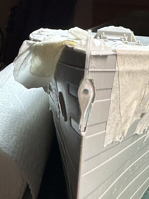
The 3d-printed part i place, with styrene shims to replace the rub rail (after much carving and shaping). The 3d part required carving to shape the fairlead blocks so that they’d transition properly into the rest of the hull.

IMG_1544.jpeg
Getting the part centered takes some patience. This angle shows the styrene shims that will eventually be formed into the rub rail. Note also that I made my vertical cut too deep, leaving a gap at the bottom. This was filled in with styrene and putty.

IMG_1541.jpeg
Aligning the part front to pack is also a challenge. You need to ensure that you have a straight bow line and that the part is also forward enough to expose the bow frame. Note the huge gaps to fill. Wee!


IMG_1570.jpeg
After the 3d-printed part has been secured in place with CA glue, I filled in the gaps with putty. I wish I built this area up more before plating since I had to deal with a bit of warping after the thin styrene plates were in place later. One option could’ve been to use epoxy putty for the large gaps. Note that I’ve etched out the areas where the styrene hull plating will be placed later to allow them to flow seamlessly into the molded plating.


The next step is the measure and cut the styrene plating to form over the 3d-printed hawse pipe. I used this approach because it made for a more realistic covering than just filling in with putty. The plating on the actual ship comes all the way up to the bow frame and the area surrounding the hawse pipe opening. The area is finished with flush riveting which makes it appear smooth. I simulated this with putty. Shaping the plates and blending them with the hull took multiple iterations with Tamaya putty and water-based filler. I used 320 grit and 600 grit sand paper as well as a fiberglass pen to clean up.

IMG_1758.jpeg
IMG_1759.jpeg
Brass anchor guards have been added below the anchor area on both sides.

IMG_1760.jpeg
This picture shows the plated and filled areas. Note also that I carved the plating below the hawse pipe at the bow to show the plating ending on top of the bow frame vs. how the model terminates them with a mythical vertical panel. There is some filling work here as well to cover my sanding marks.


IMG_1763.jpeg
IMG_1762.jpeg

I primed the area with Mr. Finishing Surfacer 1500 Grey and then went about sanding again.

IMG_1761.jpeg
I think the finished hawse pipe and fairleads look very similar now to the actual ship (below).

IMG_0215.jpeg
 
Great job you did! The quarter of an inch would not sink the ship, wouldn't it?;)
No! ;-) But it still bothers me. I should’ve double-checked. It’s at the correct height at the waterline at least.
 
Plating the Bottom of the Hull: (or Adding Details that Most People Won’t Ever Notice)

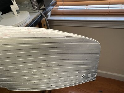
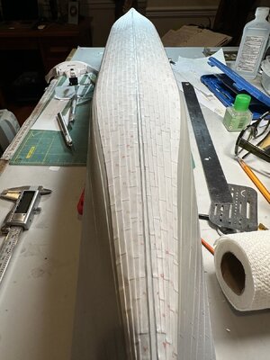
I’ve been working for the past couple of months to complete the plating on the bottom of the hull. The bottom of the hull on the model is completely smooth, which, of course, the original ship was not. Mind you, this isn’t noticeable until you actually look underneath. Depending on how the completed kit is displayed, people may never notice. The thing is, *I* will know about it. ;-) Also, the plating kit I purchased from MiniBrass provides plating that covers the area below the propeller water wings and forward of the center screw area. I felt that this finished off the plating modifications I made to the stern area.

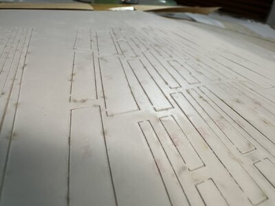
MiniBrass provides a kit that contains somewhere between 400-500 styrene plates that are laser cut on five separate sheets.


IMG_2154.jpeg
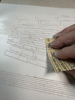
The laser cutting process creates a ridge around each piece, so, starting with Sheet 1, I sanded each sheet to smooth out the ridge as much as possible.

IMG_2153.jpeg

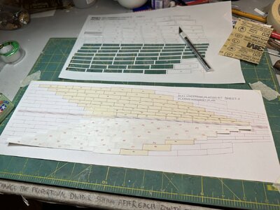
MiniBrass provides paper templates for laying out each plate. All plates are numbered in sequence with their corresponding location shown on the paper diagram. You just need to cut them out, clean up the edges and place them on the sheet. The overlaps are also indicated on the diagram. The first few plates need to be secured with masking tape to hold them in position on the paper template. I used Tamaya Extra Thin Cement to secure the plates together. This was a straightforward, if not tedious, process. A few of the plates were mis-numbered, but it’s pretty easy to identify what needs to go where.
IMG_1842.jpeg

Once you’ve laid out all of the plates for all five sheets, you can then transfer them by section to the hull, starting aft at the stern.
There is a gap along the keel that is defined for the keel plates to be laid in when all of the other plates are secured. I measured the gap from the drawings and transferred this to the pre-sanded and prepped hull using two parallel pencil lines running from stem to stern. This also helped to place each section of plating correctly on the hull. You want the plates to span from the pencil line to the plate line at the curve of the hull.
IMG_2361.jpeg

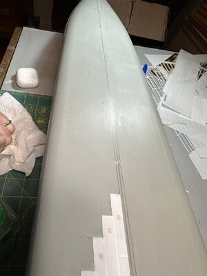
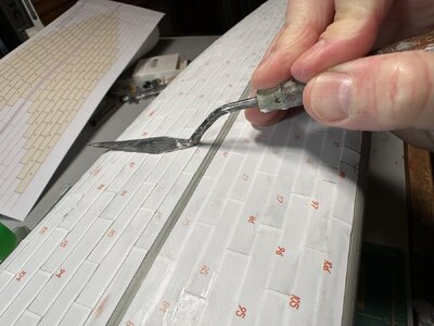
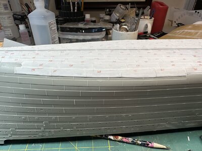
The picture above shows the Sheet 1 plates (Port and starboard) in place with Sheet 2 starboard plates added. You can see the alignment from the center pencil lines to the molded hull plating near the bilge keel area. Each new plating section needs to overlap the previous. The challenging part is getting enough cement on the hull to completely secure all plates. I ended up with sections of plating that were not secured firmly to the hull and I had to return to each area to inject more cement. I also probed the plate edges to find unsecured areas using a palette knife. The palette knife was also useful for pressing down on the plates after more cement was injected. The styrene plates are pretty thick, but you still need to be careful about the amount of cement that you use or the plates will be deformed.
IMG_2402.jpeg
IMG_2492.jpeg
This picture shows loose plating near the top of the image. This occurred all over the hull after I secured the sections. I just systematically travelled from one end of the hull to the other, looking at both sides, and injected more cement as I went. This took an enormous amount of time but it was necessary. You can’t have loose plates that will end up cracking paint later.

IMG_2478.jpeg
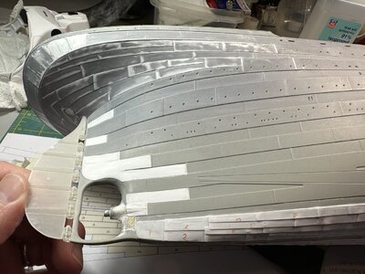
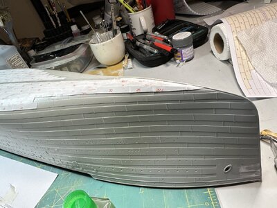
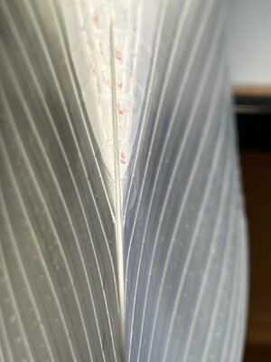
This picture shows the plating reaching the bow area. I ended up doing a lot of extra work here to help make the plating transition as well as possible into the molded portion. This will be one of the few obvious areas where the bottom hull plating will be easy to see.
IMG_2792.jpeg
The bow area after sanding and blending.
IMG_2791.jpeg

IMG_2687.jpeg
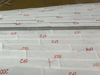
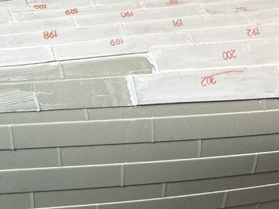
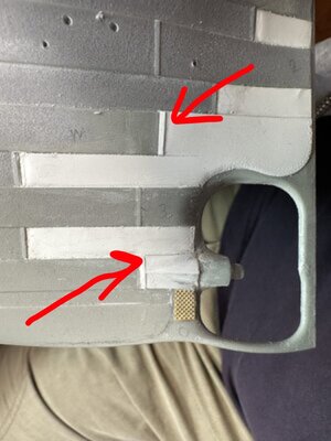
Another important part of the process was adding styrene strips to simulate plate overlaps. This helps to blend the new plating into the molded plating. Notice how plate 200 just ends abruptly? The molded plating is simulating an inner layer, yet plat 200 also overlays plates 192 and 199. I’m not sure what to do with this. I’m open to suggestions.

IMG_2686.jpeg
Another area of adjustment was adding about 2mm of additional styrene to the bottom edge of the plating where it meets the molded plating of the hull. This was likely due to how I laid my plating on the templates and/or on the hull. I imagine if you do this right it meets the molded edges perfectly. Not so for me. I cut the 2mm strips, shaped them and glued them in place on both sides to make sure there were no gaps between where the MiniBrass plating ends and the molded hull plating ends. This was eventually filled and sanded and you can’t tell that the strips were added.


IMG_2713.jpeg
The center keel plating was added last. There is no specific guidance for this. I just cut it in reasonable sections and laid it in from stern to bow.
IMG_2789.jpeg
Photo showing where the center keel plating begins at the stern, just at the beginning of the stern frame. I referenced the book “RMS Titanic, A Model Maker’s Manual” by Peter Davies-Garner to figure out where to place this. The picture also shows the sanded and blended bottom plating where it meets the lower stern plating I did previously. You’re basically looking at the main reason I purchased the MiniBrass kit. ;-)

Note that I’ve also smeared water-based putty all over the plated area and along all edges to fill and smooth in the joints. I didn’t want any gaps to show around any plates or on the edge where the sections meet the rest of the hull. I then thoroughly sanded all plating with 320 grit paper in an attempt to smooth out the plating. The styrene from the plating kit is about twice as thick as scale plating. The sanding process brings it back a bit. I will finish off the sanding with 400g and 600g to remove any scratches, etc.

Overall, I’m glad that I did this and I’m satisfied with the results. I’ll shoot it all with primer soon and I’ll post that. I find the priming process helps with plating since it shows flaws and also helps to fill in gaps. If you’re on the fence about plating the bottom of your hull, I’d skip it unless you’ve invested a lot of time in correcting the lower stern plating area. The MiniBrass plating kit shows up mostly at the bow and at the stern, when the model is displayed sitting flat.
 
Last edited:
Wow you are certainly putting in the hours on your Titanic and the work you have done so far looks great.
I am one who is sitting on the fence when it comes to plating the bottom of the hull.
I have enough work to do with fitting out all the interior spaces on mine.
 
Wow you are certainly putting in the hours on your Titanic and the work you have done so far looks great.
I am one who is sitting on the fence when it comes to plating the bottom of the hull.
I have enough work to do with fitting out all the interior spaces on mine.
Thanks! There have been many hours and I’m still working on the hull. I have the MiniBrass B Deck side plating to start soon, which should be an enormous effort - and I’ll still be working on the hull.

My overall goal is to have an accurate external impression of the ship. I’m choosing not to light it or add interior features - unless they’d be obvious to an observer. I have to draw the line somewhere. As it is, I’ll be working for another five years. ;-)
 
Plating the Bottom of the Hull: (or Adding Details that Most People Won’t Ever Notice)

I’ve been working for the past couple of months to complete the plating on the bottom of the hull. The bottom of the hull on the model is completely smooth, which, of course, the original ship was not. Mind you, this isn’t noticeable until you actually look underneath. Depending on how the completed kit is displayed, people may never notice. The thing is, *I* will know about it. ;-) Also, the plating kit I purchased from MiniBrass provides plating that covers the area below the propeller water wings and forward of the center screw area. I felt that this finished off the plating modifications I made to the stern area.

MiniBrass provides a kit that contains somewhere between 400-500 styrene plates that are laser cut on five separate sheets.


View attachment 428504
The laser cutting process creates a ridge around each piece, so, starting with Sheet 1, I sanded each sheet to smooth out the ridge as much as possible.

View attachment 428503

MiniBrass provides paper templates for laying out each plate. All plates are numbered in sequence with their corresponding location shown on the paper diagram. You just need to cut them out, clean up the edges and place them on the sheet. The overlaps are also indicated on the diagram. The first few plates need to be secured with masking tape to hold them in position on the paper template. I used Tamaya Extra Thin Cement to secure the plates together. This was a straightforward, if not tedious, process. A few of the plates were mis-numbered, but it’s pretty easy to identify what needs to go where.
View attachment 428506

Once you’ve laid out all of the plates for all five sheets, you can then transfer them by section to the hull, starting aft at the stern.
There is a gap along the keel that is defined for the keel plates to be laid in when all of the other plates are secured. I measured the gap from the drawings and transferred this to the pre-sanded and prepped hull using two parallel pencil lines running from stem to stern. This also helped to place each section of plating correctly on the hull. You want the plates to span from the pencil line to the plate line at the curve of the hull.
View attachment 428509

The picture above shows the Sheet 1 plates (Port and starboard) in place with Sheet 2 starboard plates added. You can see the alignment from the center pencil lines to the molded hull plating near the bilge keel area. Each new plating section needs to overlap the previous. The challenging part is getting enough cement on the hull to completely secure all plates. I ended up with sections of plating that were not secured firmly to the hull and I had to return to each area to inject more cement. I also probed the plate edges to find unsecured areas using a palette knife. The palette knife was also useful for pressing down on the plates after more cement was injected. The styrene plates are pretty thick, but you still need to be careful about the amount of cement that you use or the plates will be deformed.
View attachment 428512
View attachment 428517
This picture shows loose plating near the top of the image. This occurred all over the hull after I secured the sections. I just systematically travelled from one end of the hull to the other, looking at both sides, and injected more cement as I went. This took an enormous amount of time but it was necessary. You can’t have loose plates that will end up cracking paint later.

View attachment 428513
This picture shows the plating reaching the bow area. I ended up doing a lot of extra work here to help make the plating transition as well as possible into the molded portion. This will be one of the few obvious areas where the bottom hull plating will be easy to see.
View attachment 428542
The bow area after sanding and blending.
View attachment 428543

View attachment 428519
Another important part of the process was adding styrene strips to simulate plate overlaps. This helps to blend the new plating into the molded plating. Notice how plate 200 just ends abruptly? The molded plating is simulating an inner layer, yet plat 200 also overlays plates 192 and 199. I’m not sure what to do with this. I’m open to suggestions.

View attachment 428518
Another area of adjustment was adding about 2mm of additional styrene to the bottom edge of the plating where it meets the molded plating of the hull. This was likely due to how I laid my plating on the templates and/or on the hull. I imagine if you do this right it meets the molded edges perfectly. Not so for me. I cut the 2mm strips, shaped them and glued them in place on both sides to make sure there were no gaps between where the MiniBrass plating ends and the molded hull plating ends. This was eventually filled and sanded and you can’t tell that the strips were added.


View attachment 428522
The center keel plating was added last. There is no specific guidance for this. I just cut it in reasonable sections and laid it in from stern to bow.
View attachment 428544
Photo showing where the center keel plating begins at the stern, just at the beginning of the stern frame. I referenced the book “RMS Titanic, A Model Maker’s Manual” by Peter Davies-Garner to figure out where to place this. The picture also shows the sanded and blended bottom plating where it meets the lower stern plating I did previously. You’re basically looking at the main reason I purchased the MiniBrass kit. ;-)

Note that I’ve also smeared water-based putty all over the plated area and along all edges to fill and smooth in the joints. I didn’t want any gaps to show around any plates or on the edge where the sections meet the rest of the hull. I then thoroughly sanded all plating with 320 grit paper in an attempt to smooth out the plating. The styrene from the plating kit is about twice as thick as scale plating. The sanding process brings it back a bit. I will finish off the sanding with 400g and 600g to remove any scratches, etc.

Overall, I’m glad that I did this and I’m satisfied with the results. I’ll shoot it all with primer soon and I’ll post that. I find the priming process helps with plating since it shows flaws and also helps to fill in gaps. If you’re on the fence about plating the bottom of your hull, I’d skip it unless you’ve invested a lot of time in correcting the lower stern plating area. The MiniBrass plating kit shows up mostly at the bow and at the stern, when the model is displayed sitting flat.
An incredible amount of work/detail. The hull looks amazing.
 
Back
Top