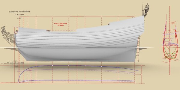
The Dutch capital ship ca. 1665 – engineering of war

Joined
Apr 26, 2023
Messages
383
Points
323

Location
European Union
.​
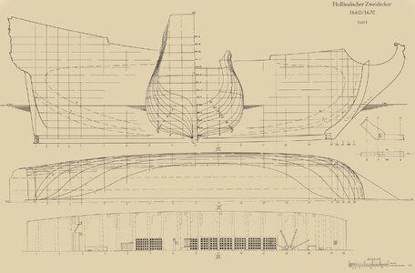
The basis for the analysis of the design method is a retrospective plan of a unique mid-17th century model of a Dutch warship, the so-called Hohenzollern model, made by taking its lines by Heinrich Winter, and published in his invaluable work Der holländische Zweidecker von 1660/1670. Nach dem zeitgenössischen Modell im ehemaligen Schloß Monbijou zu Berlin. The model itself was destroyed many decades ago, so repeating and verifying the process he performed with today's much more precise technology is no longer possible. Hence, by necessity, the present analysis must exceptionally be carried out on these modern interpreted data and not, as it should be, directly on the original source material.

In parallel, the conceptual analysis of the Hohenzollern model 1660/70 is performed in almost obligatory conjunction with the analysis of the plans and numerical data of the nearly conceptually identical ships Prins Carl & Prins Wilhelm 1696, designed in 1695 by Ole Judichær, taken directly from the precious Danish archives, and also from the paper Nordeuropæisk spanteopslagning i 1500- og 1600-tallet. Belyst ud fra danske kilder by Niels Probst, [in:] Maritim Kontakt 16/1993, pp. 30–35.

Perhaps it is somewhat too early to post, nevertheless, something is already beginning to emerge from the chaos of the various present-day misrepresentations that can be shown. On the other hand, I am not yet quite sure that this analysis can be brought to a successful conclusion, yet, by starting this thread, there is a better chance of its completion.

In the context of state-of-the-art design concepts of Dutch warships, however, it can already be said that the results, even if partial, may significantly complement the information provided in 17th-century Dutch works on shipbuilding; as it happens – one work written by a more shipwright-carpenter than a shipwright-designer, and the other by a diplomat and official who was not told everything by professionals or who inappropriately chose his source of information.


Lines plan of the model drawn up by Winter:

Hohenzollern model 1660-1670 - Sepia.jpg

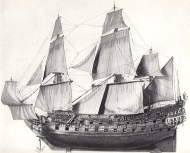
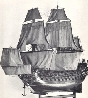
... and some of its photographs:

img271.jpg


img272.jpg

.​
 
Last edited:
.​
Master frame.


ViewCapture20240131_003755.jpg


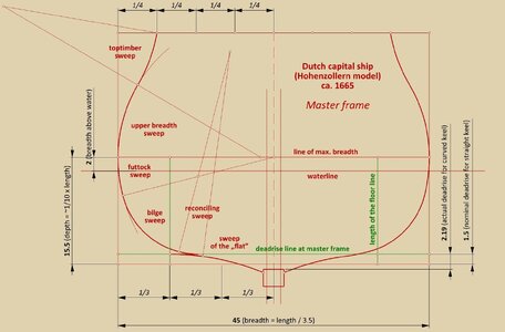
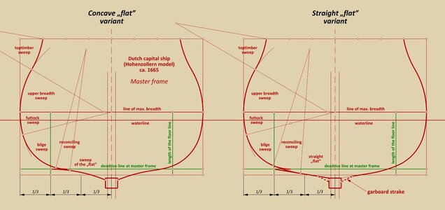
It is immediately apparent from the shapes of the master frame that this is a thoroughbred warship and not some sluggish freight wagon – the frame contours are very round and the deadrise value is large, as one would expect from a ship optimised for good seaworthiness. The futtock sweep radius is half-breadth and the bilge sweep radius is 1/4 breadth – hardly more typical values for warships. In the Mediterranean/English tradition a combination of (lower) breadth sweep and futtock sweep was used, here this combination is replaced by a single futtock sweep, very characteristic of North Continental designs, necessarily with a variable, diminishing radius along the length of the hull towards its ends, if the intended underwater shapes were to be of high seaworthiness, as for a warship.

The keel in Winter's drawing is bowed downwards (about 3/4 of a foot), which indeed was normally the practice during actual shipbuilding, thus anticipating the almost inevitable phenomenon of hogging. However, such curved keels were almost never drawn (Robert Dudley's designs of the first half of the 17th century being such an exceptional, isolated example), so depth and deadrise are counted here for a 'nominally' straight keel.

The depth (i.e. height of the design grid from the straight keel to the line of greatest breadth) is almost exactly 1/10th of the ship's length between the posts, as per a 17th century Dutch shipbuilding manual, and the nominal deadrise (for the straight keel) is one and a half feet. The ship is proportionally quite short (or, conversely, has a considerable breadth) – the ratio of breadth (45 feet) to length between posts (157 feet) is 1:3.5. This made the ship a very manoeuvrable and laterally very stable gun platform, but at the expense of speed.

The underwater part of the master frame contour was constructed in the manner already explained in my threads on this forum about Dutch ships, with the difference that here an additional smoothing reconciling sweep for all the frames was used, connecting the 'flat' sweep with the bilge sweep. Below is a description of the individual sweeps:

Futtock sweep – radius for the aft half = 1/2 x the respective breadth (variable), radius for the fore half = 5/6 of the respective half-breadth (variable)
(edit: it was later found the the radius of 5/6 of the respective half-breadth is valid for both halves of the hull, not just for the fore half)
Bilge sweep – tangent to futtock sweep and to respective deadrise line, radius equal to 1/4 x breadth = 11.25 feet (constant)
Sweep of the „flat” – arc tangent to the respective deadrise line or other auxiliary line in some other leading frames (variable radius)
Reconciling sweep – radius equal to 2/3 breadth = 30 feet (constant)

It may be added that not all leading frames are constructed in the same way as the master frame, this will be shown later.

.​
 
Last edited:
.​
Although the „flat” in the Hohenzollern model is concave, it is also important to show an alternative, at least equally common, variant with a straight 'flat', which may prove useful, for example, for those building ship models of the Anglo-Dutch wars period. Notwithstanding the difference in the resulting contour shape of both shown master frames, their entire geometrical structure remains identical, as are all their other parameters.


ViewCapture20240131_105828.jpg


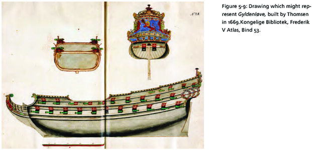
An example from this very era is still shown below featuring a straight 'flat'. Incidentally, as a result of a very low deadrise, the boxy shape of the master frame contours of this admittedly a warship (also built in the same North Continental tradition, or Dutch if one prefers), is more suitable for a merchant ship of high capacity rather than an agile warship.

Edit: Upon later investigation, it indeed turned out that the Danish ship plan below shows a privately built defensionsskib, i.e. a design hybrid of a warship and a merchant ship, in line with the Danish doctrine of increasing the size of the fleet quickly and cheaply in case of war. The ship was built in 1669 by Cornelis Thomesen at Christiania, and it was only later, in 1672, that she was sold to the state and incorporated into the fleet in 1674 (data taken from the detailed database of the Danish-Norwegian fleet – Orlogsflådens skibe gennem 500 år. Den dansk-norske flåde 1510-1814 og den danske flåde 1814-2010 by Henrik Christiansen and Hans Christian Bjerg, p. 90). This state of affairs explains perfectly the boxy outline of the ship's master frame, suited precisely to large-capacity merchant ships.


Gyldenløve 1669 - Cornelis Thomsen - Frederik V Atlas, Bind 53.jpg

.​
 
Last edited:
.​
Admittedly, the design concept of the Hohenzollern model has already been read out, but even before presenting it, it is worth highlighting the difficulties involved in analysing material that has already been interpreted by anyone (which are also the plans drawn up by Winter) and why this should only be done as a last resort, or at least why such present-day interpretations must be verified by confronting the source material as rigorously as possible.

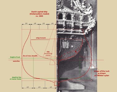
In this particular case, a good example of such a pitfall is the shape of the tuck, which for some reason was completely spoiled by Winter. It can be assumed that the reason for this was some sort of misreading of the model's hull shapes in its aft section, followed by an attempt to unskillfully smooth these shapes with waterlines at all costs, even at the expense of replacing the original tuck shape with a completely different shape invented by Winter. It may also be added here that the very attempt to design and correct hull shapes for ships of this period by using smoothing waterlines is contrary to the practices of the time, produces incorrect results as a rule and, for these reasons, cannot replace historically proper design methods.

Be that as it may, the graphic below shows both variants of the tuck shape. One according to the plan by Winter (in dashed line), and the other based on photographs of the model and design rules of the period.


ViewCapture20240201_204142.jpg

.​
 
Hi Waldemar,

Could the difference between in the concave flat and the straight flat design of these ship be the result of their building methodes.
The concave flat being the result of the southern build ships in Maze and Zeeland. The straight flat being ships build in Noorderkwartier. Noorderkwartier were still using shell first which is far easier to create a flat shape then a concave shape of the flat. Would be interesting to see where these designs were build to determine which possible methode was used.
For sure Prins Willem with its concave flat was build in Middelburg Zeeland probably using frame first construction. As far as I know for Hohenzollern it is not known where the model was build and if it qas a frame first or shell first design.
 
.​
Hi Maarten,

Probably the best and at the same time unequivocal answer to this dilemma can be found in Witsen's 1671 work on page 67 (for other readers, I will add for the sake of certainty: this work describes the bottom-first method, i.e. the one used in the north of the Netherlands). Here I will quote a translation by Alan Lemmers from Ab Hoving's invaluable book, Nicolaes Witsen and Shipbuilding in the Dutch Golden Age:

The bottom [or „flat”] furthermore, rises and descends, is made sharp or flat, to one's pleasure, and according to the use of the vessel.

The context of this statement leaves not the slightest doubt that what is meant is the cross-sectional profile of the „flat”. Nor, in my opinion, is there the slightest reason to believe that any method was somehow handicapped and prevented some intended, needed shape from being made, otherwise such an inflexible method would have been immediately abandoned, and certainly would not have gained as much popularity as precisely the „bottom-first” method.

By the way, this whole passage from Witsen's work is extremely instructive as far as these very aspects of naval architecture are concerned, or more precisely: about the excellent awareness of shipwrights of the time of the close relationship between specific hull shapes and the behaviour of such differently shaped and proportioned ships at sea.

Taking all this into account, unfortunately, it is rather impossible to answer the question (at least I cannot) whether the Hohenzollern model was built according to the "bottom-first" or "skeleton-first" method of building, since in the sense of being able to obtain a variety of shapes, both are actually equivalent.

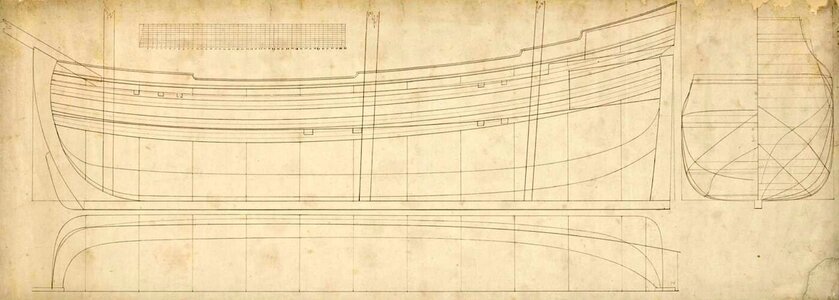
Below I also include a plan of the fluit Fortuyn from 1740. Although from a later period, it illustrates the case in point very well. The ship is definitely designed to be built by the „bottom-first” method, since it has clearly defined the "flat", bilge and futtock areas, and yet the "flat" cross-sections have all the desired shapes throughout the length of the hull: straight, convex and concave.


Fluit 't Fortuyn 1740.jpg

.​
 
Last edited:
I enjoy CAD and math and find the analysis very interesting. But this seems to give only the mid-section of the ship, and wonder how that then proceeds to the fore and aft frame shapes. Also, a small question: Do these dimensions include the hull planking?
 
.​
Do these dimensions include the hull planking?

As a rule, the contours of the frames were always designed, although it must be added that sometimes, in certain regions and for certain dimensions, the thickness of the planking was also taken into account. This was, for example, the convention for giving the breadth of the hull in seventeenth-century England, although this is already a resultant value and not strictly conceptual. But indeed, it is always worth being careful.


I enjoy CAD and math and find the analysis very interesting. But this seems to give only the mid-section of the ship, and wonder how that then proceeds to the fore and aft frame shapes.

!??? Signet, why do you consider this thread already closed? Do you know something that I don't already know about? :)


Wow…thanks! I am learning a lot here…

Thanks a lot, Jim. Yes, that is precisely the intention... one of them. Thanks again. :)
.​
 
Last edited:
.​


As a rule, the contours of the frames were always designed, although it must be added that sometimes, in certain regions and for certain dimensions, the thickness of the planking was also taken into account. This was, for example, the convention for giving the breadth of the hull in seventeenth-century England, although this is already a resultant value and not strictly conceptual. But indeed, it is always worth being careful.

!??? Signet, why do you consider this thread already closed? Do you know something that I don't already know about? :)
No, of course not. I was just wondering how the mid-section will morph into the very different bow and stern sections. And I'm sure you will cover this.
 
.​
Have you copyrighted your work?

That's an interesting question. Generally, copyright in my country (and probably everywhere else) contains two elements: the so-called moral rights, meaning who invented or discovered something, which are inseparable from the creator (they cannot be sold, waived, lent, bequeathed, etc.), and the so-called economic copyright, which can be treated as any commercial commodity.

However, the specific nature of my discoveries (in technical terms) means that they are devoid of this second element, i.e. of a proprietary nature, which precludes, for example, the application of these discoveries to the patent office as inventions of a technical nature (or at least I treat them as such). Only the wording of the text (like any literary work) and the graphics shown are protected by law itself, and from a legal point of view they are treated like any creative work of artistic nature.

It follows that the very ideas I am showing can be used quite freely, and only the verbatim quotation of the text or the reproduction of these graphics requires the author to be cited (although in practice this is more a matter of decent behaviour). In my country, it is possible to quote virtually without restriction, and also in terms of the extensiveness of the quotation, provided that the quotation is for educational, research, popularisation, scientific, etc. purposes (i.e. non-commercial).

.​
 
Last edited:
.​
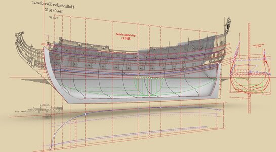
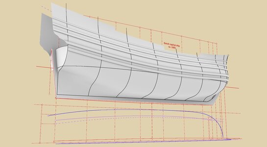
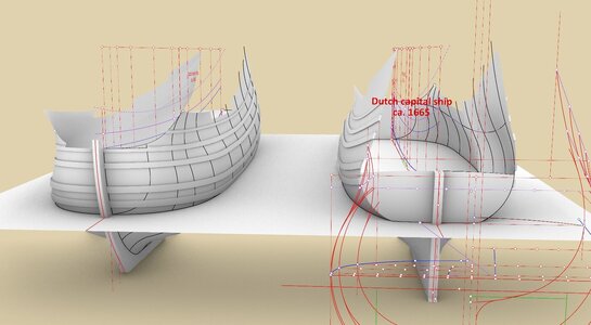
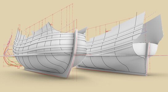
Below are some final renders from a work that has actually already been completed. It turns out that the "classical" hull forms of 17th-century Dutch-style ships can be designed as much as possible in accordance with the true shipwright art, i.e. in an engineering manner. What is more, the understanding of the set of design tools used at that time and specific ways of their application, combined with an apt modification of individual design parameters, makes it possible to obtain practically "any" hull shape according to the designer's intention, depending on the purpose of the vessel under construction, its expected sea-going or economic properties and even current aesthetic trends.

The engineering way of designing ships does not necessarily equate to making (complete) graphic designs on paper beforehand. In most cases, especially the simpler or routine ones, the plotting of, for example, the contours of the individual frames could and indeed did only take place to actual scale on the mould loft in the shipyard.


ViewCapture20240210_093101.jpg


ViewCapture20240210_094641.jpg


ViewCapture20240210_095200.jpg


ViewCapture20240210_095314.jpg


ViewCapture20240210_095541.jpg
.​
 
Back
Top