TEV Wahine 1/35 Large Scale RC build

Joined
Dec 15, 2023
Messages
114
Points
103

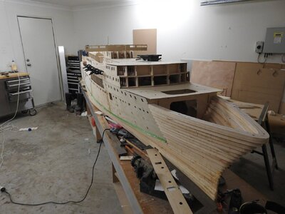
I have been building this model for 2-3 years now and had a build on another site but due to requests I have decided to do a build of sorts on here as well but will spend some time just getting everyone up to speed as its a complex build and lots to grasp.
This is not for the faint hearted,
First off the most common questions I get .

Why this ship
Because she is a stunning looking ship and has ties to my family and personal history. also I was presented with a very unique opportunity to catalogue all the Union Steamship Company plans for the archives and also had some left to me my the designer of the ship so in a trade I gave them mine in return for what they had.
In short I have over 400 actual shipyard plans and hundreds of slides and photos from the archive and personal collections.

Why so Big
I have in the past built a number of hulls for test tanking use for naval Architects and wanted to have a model that behaves on the water correctly and starts to produce a wake and bow wave correctly, so doing it at test tank size seemed logical, I know many will question my sanity on this.
The other reason is when you have soo much detail on a ship that you don't have to guess anything you need to or owe it to the job to do it right and in my opinion to get it all in it needs to be a large scale.
I don't live far from my local model boat club lake (5min drive) and will have a custom case and trailer made for it.

OK the ship
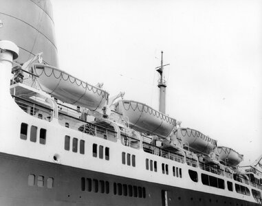
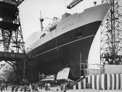
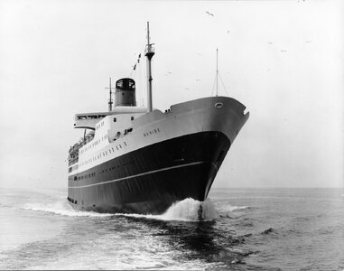
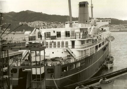
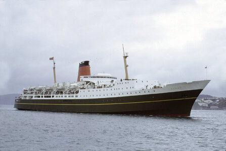
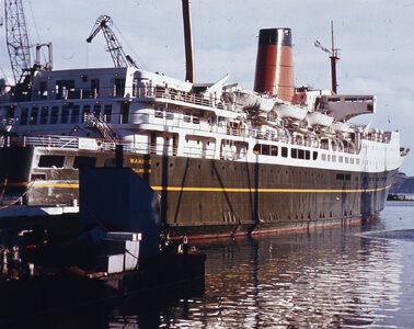
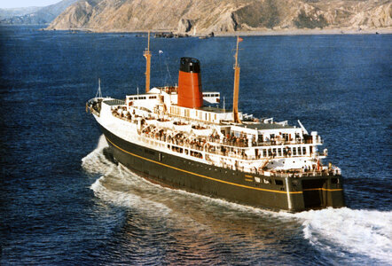
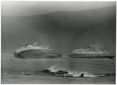
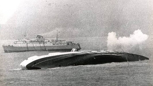
She was the largest RoRo vessel of her time built in 1964-65 at Fairfield's in Govan Glasgow to do the Wellington Christchurch run in New Zealand she foundered in 1968 with the loss of 52 lives due to being caught in a cyclone and overwhelmed.
My parents worked for the USSC who owned her and my father built a couple of models of some of their ships for the company.
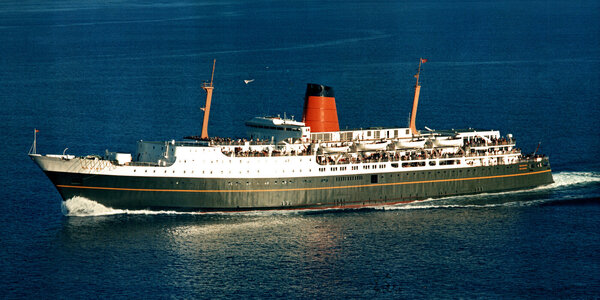
Wahine Aerial.jpg

The research involved in this project has been over 10 years of my life and goes as far as getting samples of paint from artefacts from the ship and getting it analysed and the paints reconstructed and made, painted out to fade and then matched to a model friendly form.
I found the masts in 1985 and had them conserved so was able to get that colour that way.
The models my father did were painted from the paint in the ships paint lockers, so was able to find those at Otago Museum in NZ and get those colours that way, the rest were in the paint spec document for the ship.
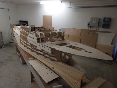
I will put up some images of the model as it is now and will then cover it in sections, like interior spaces, running gear etc
 
Last edited:
The Hull
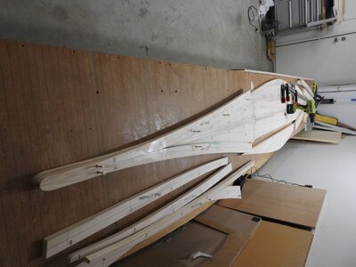
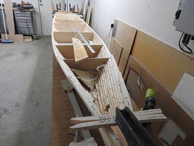
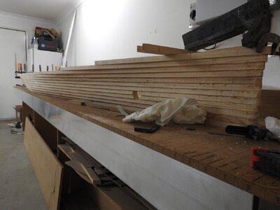
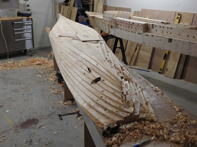
With a displaced weight of 195 kgs this needed to be very strong while keeping the model centre of gravity low, I opted for Bread and Butter up to the knuckle and plywood everywhere else.
The model itself will weigh about 60kgs,the rest is ballast.
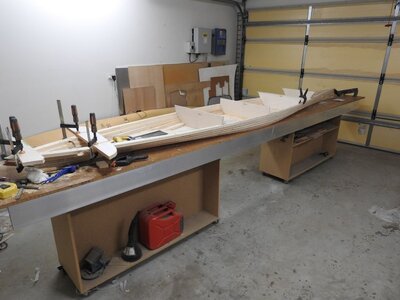
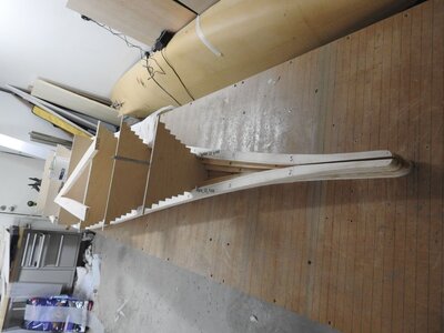
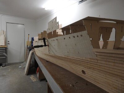
I devised a way of building this with each layer of the hull in multiple parts with staggered joints, the joints fall at set places like a 3 step laid deck, stepped bulkheads support the joins at those point to keep it all aligned, as you will see it worked well.
To build this from single wide planks would have been astronomical in price as the model has a beam of 600mm and even 300 mm wide boards are very hard to do.

The plans

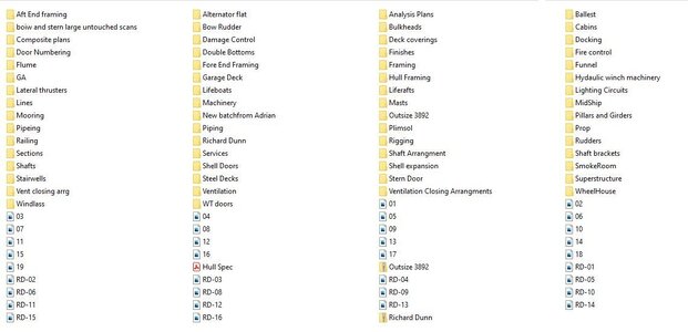
Each of these folders has a whole set of drawings.
plans.JPG.db5a1c1db837249ce8aea24a37f43904.jpg
Like this
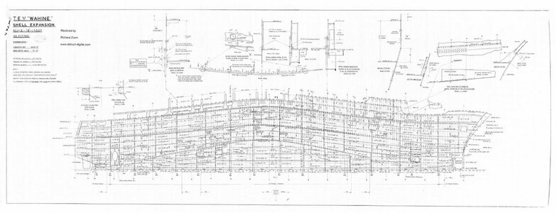
2000735893_TEVWahineShellExpansion.thumb.jpg.ca891d18efad5acd8572c2bed4f74aff.jpg
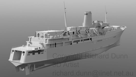
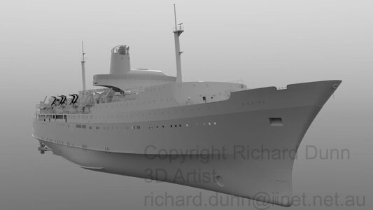
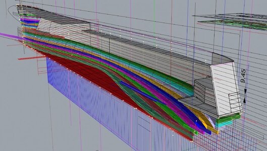
The model was then done in 3d over about 12 months
2051326034_PromoShotAft.thumb.jpg.e64777f12380312291e69394b46c18cf.jpg
826607523_PromoShotForeward.thumb.jpg.39f0e406004373a2b789c77a6ab92f08.jpg
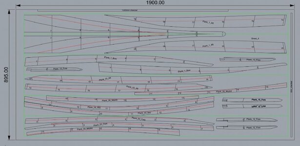
The bread and butter layers where planned in 3d
894491.jpg.bb156010db7ab273e885d4fed0a9a4a1.jpg

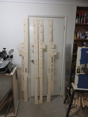
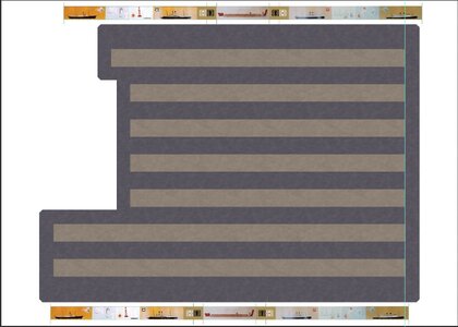
And the layouts on the sheets were printed onto drafting film and glued to board and cut out.

894493.jpg.6a9825621c1e3d640715c5c2d7c70ead.jpg
894652.jpg.87d016fa6355033eca95291eecd129eb.jpg
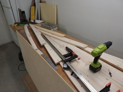
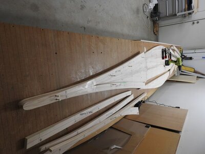
The hull was then epoxied and screwed together paying attention to the keeping the layer flat and level with straight edges.
894651.jpg.ae33e01630d835e44892bfa3ee8a6ee2.jpg
895128.jpg.6cda48d8e44956fc251583e2d63a0aa6 (1).jpg
894795.jpg.1910fef6cace53ccfb2c95dc92228254.jpg
DSCN9065.thumb.JPG.46cba15d9c17e577aa1ae55a0c01baf3.jpg
sheerbow.thumb.jpg.0dd9bd6408fd8c42aa9ef2462cb6332f.jpg
lams.thumb.jpg.1552e804b279cfb3c3794afa3896ebe7.jpg
DSCN9065.thumb.JPG.46cba15d9c17e577aa1ae55a0c01baf3.jpg
DSCN9073.thumb.JPG.dbcb73736d3c2f75c1da685ec9db2000.jpg

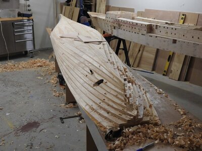
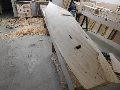
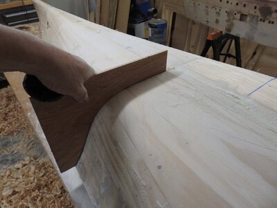
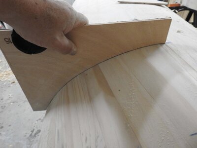
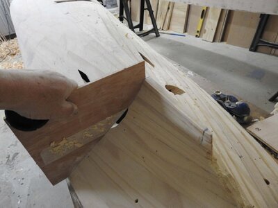
Template were cut on CNC and the hull made good as far as lines go.

DSCN9077.thumb.JPG.1de80b0ce3a119f15c482e61f75caadd.jpg
DSCN9079.thumb.JPG.84ced91d9e947f33b236c86360f1e236.jpg
DSCN9078.thumb.JPG.c3c94827027da77e92f0e8236f94fe80.jpg
By this time the upper works had also been built but I will arrange this by part.
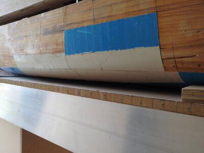
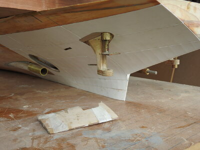
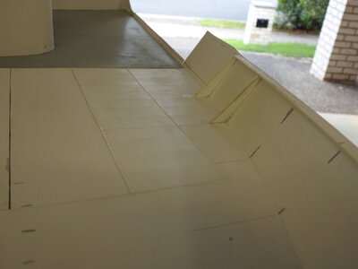
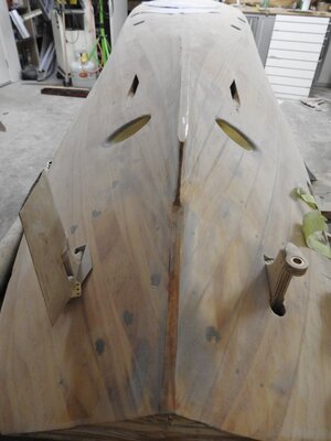
The hull is then going to be plated, I found way to shape the plates in 3 axis and still get the tin-canning affect from welding.
weld seams are also done to scale.
DSCN9664.JPG
DSCN9667.JPG
The same effect of the Foredeck note bulwark stays with bent flange and clearance holes included.
DSCN9666.JPG

I have used Starbond CA to bond the plates on and after a rest period of nearly 9months in extreme heat it has no sign of coming off, I cant get them off if I try.
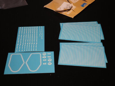
Draft numerals, hull rivets and name lettering including Plimsoll have been custom made for me by Railtec in the UK and are amazing, they are resin printed 3d waterslide decals, I designed the files for them in cad and they made them

DSCN9065.thumb.JPG.46cba15d9c17e577aa1ae55a0c01baf3.jpg
 
Last edited:
You’re a talented model builder Richard.
Its nice of you to say so Brian, But I am good at hulls, the detail I struggle with hence why I limit myself to large scale.
I have been a furniture and guitar builder for most of my life so the woodwork part comes easily when tied with the 4-5 years I spent in Naval Architecture it's a bi product of my old career I guess.
But thankyou for the compliment all the same.
I am in awe of people who can do the POF built up models from scratch, I started one of Le Gros Ventre last year but the book from Ancre was missing plans and they have not responded to my request for replacements.
I am not sure I have what it takes to do one of those
 
I was going to share a couple of builder plans showing the plating and longitudinal/transverse framing of some decks but they are too big for upload, I don't want to put up downsized versions..
I should say to that the archive are wanting to find a home for the entire collection of USSC ships plans if someone can get it sorted, MSW were approached but could not make a decision on how to host them and lost out.
Here is one of the collections of one of the ships my father built the model for that have been uploaded.
there are about 58 vessels in the collection!.
 
Here are the 3d printed decals for the Wahine model.
all.jpg
These are rivets, yes even a welded ship has rivets from time to time as seen here in a photo, the numbers are depth marks for the hull.
High res004 copy.jpg

The ring arrangement at bottom left is the rivets for the rudder horn seen here in this photo, even these I have plans for.
Wahine screws exp.jpg
115 DD3 copy.jpg
The slight raised effect of the decals is seen here...... hopefully.
rudder rivets.jpg
I can highly recommend this mob for this work, but be prepared for a long wait..
 
Last edited:
One more quick post about externally made units before I go and do some actual work on the bench.
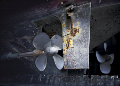
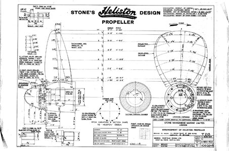
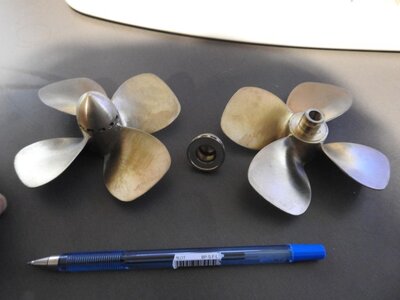
The propellers of Wahine were made by PropShop in the UK from the actual plans and were cast from bronze.
Heliston Design Propeller.jpg
The props for the model. and yes they were pricey but they are beautiful... check against photo above of them 2 posts back. these are about 100mm dia
676288.jpg.8f46bb7815d2640c498f03f972083af4 (1).jpg
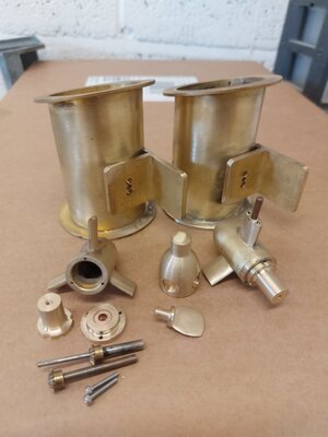
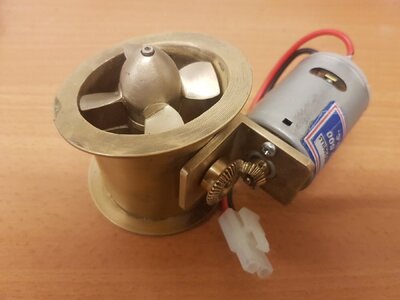
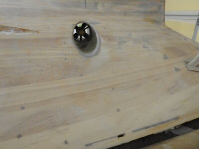
The lateral thrusters also were made by him and they are exact replicas of the real thing and they work.
These about 50mm dia inside tunnel
20220203_153334.thumb.jpg.4dfdb54e554ba1647dc049bcd5046a58.jpg20220215_164000.thumb.jpg.9bc1f1cb8b4ce31f457217cdd30c0d76.jpg
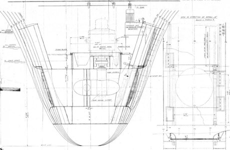
One of the 5 plans of his part
plan.thumb.JPG.0c997a20568e67531419b2cd62c4c76e.jpg
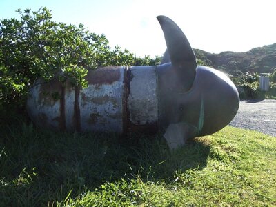
and one of the real props.
IMGP1861.thumb.jpg.6bdef79a80184c733096853d43507bc2.jpg
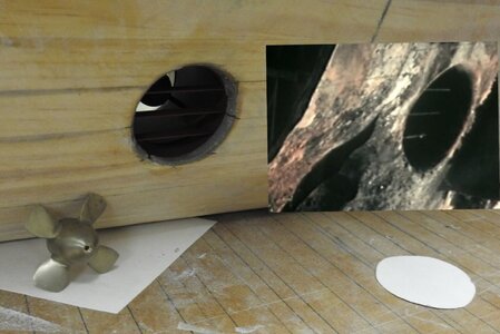
Some shots of them being installed in model
DSCN9514.thumb.JPG.8bf93de4f1d25b73af0ffe6b7c4de8f7.jpgDSCN9513.thumb.JPG.ac5c3d8e5146457381e0ee614b8e5794.jpg
Starting to solder grates over the bellmouth of the tunnel, the image at right is the real one taken from salvaged wreckage
tunnel.thumb.jpg.f1ba175a1842a6164dc9c9326df9e77e (1).jpg
 
Last edited:
Richard H Dunn amazing, passionate, project! I’m in awe for two reasons… first because of your talent on so many levels, 2nd… you get to see the Southern Cross as much as you’d like. Keep’’em coming.
 
Thanks guys

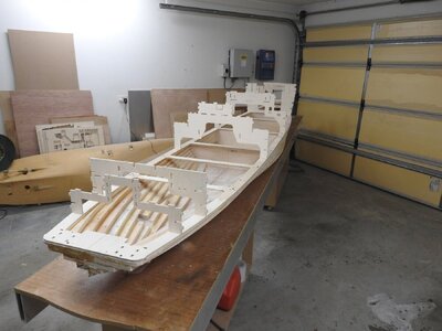
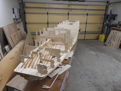
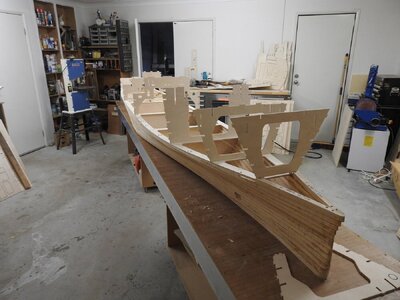
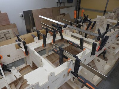
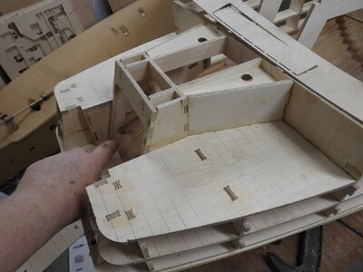
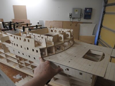
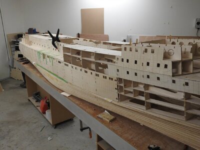
Ok the next stage was the upper hull and superstructure, rather than build them as separate parts I opted to divide them where the "lid" goes to access the hull.
I will just do an image dump here is sequence, more or less as it's self explanatory.
A LOT of planning went into sequence and what needs be accessed as well as cable routes and making sure holes are provided to feed wires through
DSCN8661.thumb.JPG.cfeca5cdef9689c80dbfff6eab5eb0b6.jpg
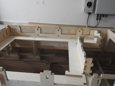
The Base plate is seen here that fits the top of the carved portion, it has the frame slots cut in it for accuracy, this part is not glued down as top part needs to be able to lift off for a while until motors etc are installed.
DSCN8666.thumb.JPG.c07b6cfdd5bc10e15db0d6f9bf9bcc6a.jpgDSCN8662.thumb.JPG.70da539bd39327ca777644d1d75b1e03.jpg

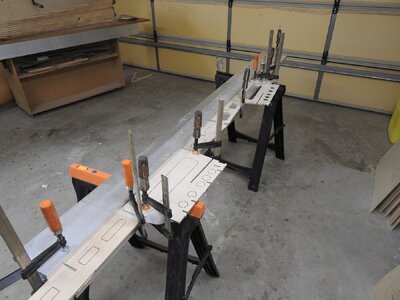
The longitudinal girders needed to be glued up against a straight edge.
DSCN8667.thumb.JPG.b2464e70ba53c6d7b8d93697ded2eeab.jpgDSCN8708.thumb.JPG.c0dce6603d15717b606d08109a89158a.jpg
Then the whole assembled
Seen below is the ships smoke room, it will be fitted out internally as the windows are large, the central section lifts out to motor room.
DSCN8703.thumb.JPG.56d0cfe66142a07ee37df539ce2e6ddd.jpg
The aft mooring deck, I am pointing to the rudder locations and access through the stern door.
DSCN8734.thumb.JPG.7154a3940f622b670f3e39453fea84cf.jpg
DSCN8731.thumb.JPG.f1bcd85093566c7af9dc2da120b9928e.jpg
DSCN8781.thumb.JPG.5e062842f76125747b43422caae82150 (1).jpg
The bow blocks assembled
DSCN8810.thumb.JPG.9efc981e08d83308684f9196f194ae02 (1).jpg

DSCN8732.thumb.JPG.71118a908cf7c63e652efd823d1e1548.jpg

DSCN8670.thumb.JPG.68d7938edd622cb0a919075843c344a3.jpg
 
Last edited:
Now Internal spaces

The ship has 4 areas that need to be fitted out with interiors aside from the Mooring decks aft and the Promanade deck .
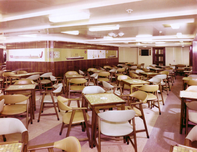
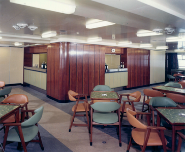
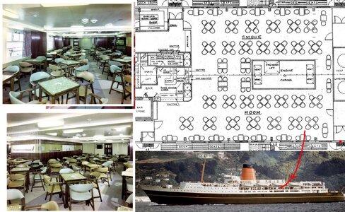
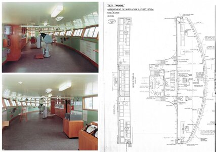
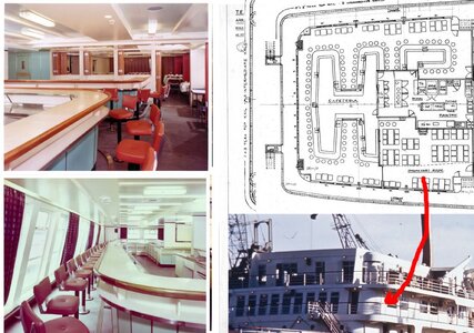
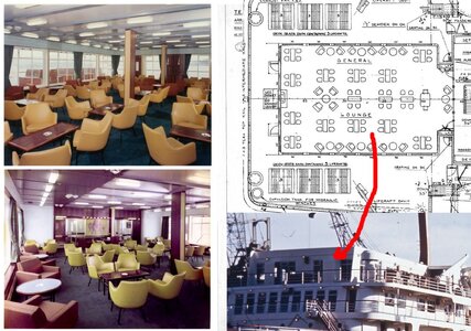
These are the Smoke Room, Wheelhouse, Cafeteria and Main lounge, all will be finished and populated with furniture based of the interior photos and GA plans for the respective spaces, the surfaces are done on heavy paper, all the surfaces like Lino and Formica are printed on A1 sheet and will be glued to the ply and varnished.

Smoke Room
The printed files for the floor and murals on the engine casing murals.
1948559497_snokeroomfloor.JPG.cda9da9c4773a29634565599dfa1a2bf.jpgSmokeroom_panels.JPG.f42a2bab8c49a14ad84790eb18a1cc1c.jpg
Two photos of the space on the ship
1485282983_SmokeRoom_06.thumb.png.54b7b8f6d5dd00058ac823c4daac891e.png1843143187_SmokeRoom_04.thumb.png.471d59fb63f802b42800c0960cf059f4.png
The space on the model
DSCN8819.thumb.JPG.b7389195589bc1c5ab04415a65843321.jpg
684504.jpg


The Wheelhouse/Bridge

684502.jpg
The Cafeteria
684503.jpg
And the aft lounge which has big 60mm windows, nowhere to hide with this, I will use flocking for the carpet.
684501.jpg
 
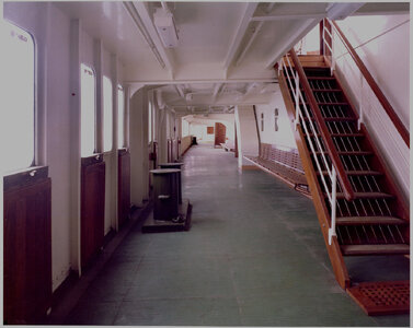
The open areas of the ship such as the promanade and mooring decks aft will have all the framing built as well as it will be seen and I think makes or breaks the model
The Stbd promanade deck on Wahine looking aft This will all be done with Styrene
Promanade Deck Looking Aft.jpg
No photos exist of the inside of the aft mooring decks but I have the construction plans for that unit.
 
Wow what an amazing build, that scale is off the charts and the research you have put into this is amazing.
I would never attempt anything near this scale so happy to watch a master at work.
If I remember correctly hearing about the sinking on the news and the bad weather as we had a day off school and that was in Masterton.
 
the research you have put into this is amazing.
Yeah it's the culmination of a life long interest really so the research is enormous. 40 years in reality, but actual targeted research where I went looking about 3-4 years.
I am no master.. trust me I still get overwhelmed and look at others work to inspire me just like everyone else, so master...definably not.
 
Well if you're not a master builder I'd sure like to know who the hell is? I never realized how indepth boat building could be. It's amazing how much is to be considered before even starting to build a ship or a model. What sort of engines will you be using for this model? The mechanics of their installation will be very interesting to see.
 
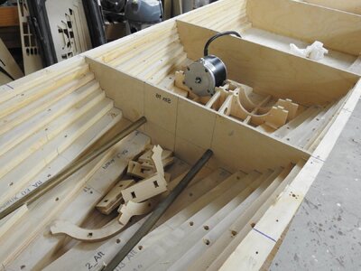
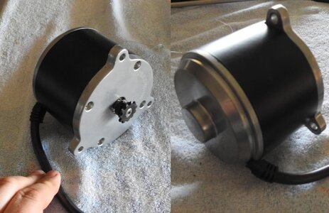
Motors are Ride on Scooter motors that require 24 volt batteries to run, here is one while I fit the mounts which will be glassed in. The prop shaft is continuous from the motor room bulkhead to the prop itself which makes the A bracket visual only, the shafts are totally to scale but enclosed over whole length so luckily it was possible on this ship, basically its the same setup as a smaller model, a shaft with bronze bearings at each end and a grease nipple in top.
the rest is all visual to make it look proper.
I was going to use 4 x12 volt batteries about 8 AH but am considering Lithium packs now, just scared of fire risk...not to mention 24v Lithium batteries are between $1000-2000 each.
Believe it or not the finding the batteries has been the hardest part of this build for me..so if anyone has suggestions please shoot.
Here are the motor specs.
I should add the motor specs were given to me by the guy who built the props, as I am not great at that sort of thing.


267296682_DSCN9146copy.thumb.jpg.fd1df9a30186f34b5ab16b177238c413.jpg

665864.jpg.001c22e277c44fdfcbff3c32186ad11d.jpg
H
 
Last edited:
Back
Top