
Great information here Dave. It'll be a nice project. Kudos to all you guys who have jumped in to CAD and CNC. Its not for me but I have to respect the effort it takes.

You are using an out of date browser. It may not display this or other websites correctly.
You should upgrade or use an alternative browser.
You should upgrade or use an alternative browser.
Tecumseth 1815
- Thread starter Dave Stevens (Lumberyard)
- Start date
- Watchers 15
-
- Tags
- tecumseth
- Joined
- Dec 1, 2016
- Messages
- 5,146
- Points
- 728

Great information here Dave. It'll be a nice project. Kudos to all you guys who have jumped in to CAD and CNC. Its not for me but I have to respect the effort it takes.
thanks for viewing the thread
for me who is doing the design work, drawings and 3D modeling i see it in my head but for me to show others 3D modeling helps a lot. The Tecumseth has unique joinery at the stem and keel so lets take a look at it.

This is a view of the side with the stem to the right that curve you see is an inset for a iron brace

what i did was swing around to the other side so the stem is now on the left. Notice it is totally different than the other side in the image above.
lets take a couple more views
in the last view you can see the inset for the iron brace.
No doubt about it this is joinery that makes you stop and think, its a challenge indeed to pull off.


- Joined
- Dec 1, 2016
- Messages
- 5,146
- Points
- 728
now i will move the stem piece and add the apron this is a nice feature where i can remove pieces or view the structure as an x ray

ok the stem has been removed from the keel


adding the apron to the keel

now it becomes clear what that cutout is for at the end of the keel. It is where the end of the apron sits in.


lets walk around to the other side

on this side you do not see the joinery between the apron and the keel.

now lets put the stem back in place


ok the stem has been removed from the keel
adding the apron to the keel
now it becomes clear what that cutout is for at the end of the keel. It is where the end of the apron sits in.
lets walk around to the other side
on this side you do not see the joinery between the apron and the keel.
now lets put the stem back in place
- Joined
- Dec 1, 2016
- Messages
- 5,146
- Points
- 728
how far do you go to adding detail that would never be seen?

In the case of the stern post there is a mortise and tenon do you cut the joinery? it will never be seen unless someone takes the model apart.
For this project there are two models being built one is a virtual model which is requested by the museum and virtual models can be disassemble to view all the joinery and the construction used to built the ship. So yes everything has to be done right down to the nails. As far as building a display model for personal or for a client like a museum that is a detail the museum may or may not request, in the case of anyone building this model if you want to challenge yourself well go for it. The information is provided it's up to you what to do with that information.
Last edited:
That’s some joinery indeed. I wouldn’t attempt it. Very strange design. How much detail to add to a model when it won’t be seen. I used to think add it anyway. In my older and wiser ! age Im of the school if it surely will never be seen don’t do it. Opinions like mileage may vary.
- Joined
- Dec 1, 2016
- Messages
- 5,146
- Points
- 728
That’s some joinery indeed. I wouldn’t attempt it. Very strange design. How much detail to add to a model when it won’t be seen. I used to think add it anyway. In my older and wiser ! age Im of the school if it surely will never be seen don’t do it. Opinions like mileage may vary.
i agree there is no need to add unseen detail like a mortise and tenon but i do document the fact it is there. If this were a printed article i would include "The stern post of the Tecumseth had a mortise and tenon in the top of the keel", in this build log it is shown in the virtual model. I have read so many archaeological reports that document every last detail which adds to the overall understanding of the structure and how it is built.
- Joined
- Dec 1, 2016
- Messages
- 5,146
- Points
- 728
assembling the keel first the 3D model
the stern post, inner post, deadwood and rising wood are set in place.

moving to the bow, the apron fits into its notch in the keel


the the next part of the stem

it sits on the false keel, butts against the front of the keel and under the apron.

and it looks like this

next piece

A tricky fit it has to sit on top of the part below and match up with the hook scarf in the apron. If you are slightly to high or low on the bottom piece the hook scarf will not match up. Easy in virtual reality it is just a select and fit much harder in actual reality.

the stern post, inner post, deadwood and rising wood are set in place.
moving to the bow, the apron fits into its notch in the keel
the the next part of the stem
it sits on the false keel, butts against the front of the keel and under the apron.
and it looks like this
next piece
A tricky fit it has to sit on top of the part below and match up with the hook scarf in the apron. If you are slightly to high or low on the bottom piece the hook scarf will not match up. Easy in virtual reality it is just a select and fit much harder in actual reality.
- Joined
- Dec 1, 2016
- Messages
- 5,146
- Points
- 728
moving on fitting the deadwood at the bow

the forward piece of the rising wood (yellow) scarfs to the end of the the piece sitting on the keel

like this

then the upper part of the deadwood scarfs to the rising wood and sits against the inner face of the apron. In actual building i would join the upper part of the deadwood to the end of the rising wood first then fit both of them to the apron and keel, or you would have to slide the scarf of the deadwood between the rising wood and apron.

the forward piece of the rising wood (yellow) scarfs to the end of the the piece sitting on the keel
like this
then the upper part of the deadwood scarfs to the rising wood and sits against the inner face of the apron. In actual building i would join the upper part of the deadwood to the end of the rising wood first then fit both of them to the apron and keel, or you would have to slide the scarf of the deadwood between the rising wood and apron.
- Joined
- Dec 1, 2016
- Messages
- 5,146
- Points
- 728
and that is all to the keel pieces the last pieces are the keelson and they are added after the frames are in place.


- Joined
- Dec 1, 2016
- Messages
- 5,146
- Points
- 728
going back to the bow there is a hole between the keel, apron and gripe, below is a wedge

i took the wedge and placed it in the hole just like this

why is there a little wedge shaped piece? why didn't the shipwright shape the main parts to fit together? actually there are two wedge shaped pieces the second one i did not show it is between the top of the keel and the rising wood. The answer is "i don't know why there are wedges" but here they are.
Anyhow the last piece is the iron U set into the the wood parts

it sits into the recess, there is one on each side and the U also holds the wedge in place. Could be there are spikes that were run down through the wedge and into the gripe. Don't know that and no one is going to take apart the wreck in the museum to find out.

flush with the surface

i took the wedge and placed it in the hole just like this
why is there a little wedge shaped piece? why didn't the shipwright shape the main parts to fit together? actually there are two wedge shaped pieces the second one i did not show it is between the top of the keel and the rising wood. The answer is "i don't know why there are wedges" but here they are.
Anyhow the last piece is the iron U set into the the wood parts
it sits into the recess, there is one on each side and the U also holds the wedge in place. Could be there are spikes that were run down through the wedge and into the gripe. Don't know that and no one is going to take apart the wreck in the museum to find out.
flush with the surface
- Joined
- Dec 1, 2016
- Messages
- 5,146
- Points
- 728
really the wedges are there on the real ship, Why they are there i have no idea maybe a mistake in cutting the timbers maybe the angle was off for the stem when setting the bow timbers, maybe they were used to set the correct angle of the stem. Maybe because they just did not have a big enough piece of wood. This ship was not built in an established shipyard it was built on a farm in the wilds of the Great Lakes frontier so Robert Moore could not just go out and get another piece timber.

a little detail that could very well be over looked or to small at 1:48 scale but at a large scale they are drawn on the plan.

interesting is you see two wedges on one side but only one wedge on the other side.

a little detail that could very well be over looked or to small at 1:48 scale but at a large scale they are drawn on the plan.
interesting is you see two wedges on one side but only one wedge on the other side.
- Joined
- Dec 1, 2016
- Messages
- 5,146
- Points
- 728
now that the virtual keel is done it is time to cut wood and build it in reality first the sheet stock is cut to size 3 1/2 wide and 32 inches long and .308 thick. Red Maple
now some CAD users like working full size i personally i draw at the scale i want to build the model because if you are drawing full size you can not fit the parts on the sheet stock. I need to know right from the start how big the sheets are and what i can fit on each sheet. You can not work full size and scale it all down that does not work. The parts are nested together to fit a sheet. Also you do not want to use to wide a sheet because wood will move and the wider the sheet the bigger the chance it will cup or twist. so fitting parts as close as possible is the key here.
It is so nice i can take the original drawings and build a 3D model, CNC parts or laser cut parts.
There are limits to what can be done by machine as you are about to see.
- Joined
- Dec 1, 2016
- Messages
- 5,146
- Points
- 728
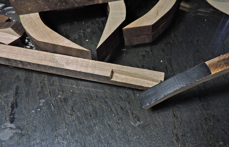
these are the two parts i am going to be working with

and what i want to do is cut this notch
i could etch the notch with the laser or use a mill and cut the notch, I do have a X,Y table and a drill press to mill out the notch but there are a lot of model builders who do not have that setup so i will cut the notch by hand deminstrating you don't need a mill or milling setup all you really need is an exacto blade.

To do the setup i printed out a drawing of the stem and poked pins at the bottom of the keel and along the outer edge of the apron. I did this to locate the parts.

i placed the keel and the apron against the pins. using a scrap piece of wood to keep the apron level with the keel. It looks like the apron does not match up with the drawing but it is only the angle of the camera.


Using a piece of blue colored masking tape on the keel and adding weight to hold the parts in place i cut along the edges of the apron. The masking take gives me a sharp clean edge.


now i am ready to cut the notch
and what i want to do is cut this notch
i could etch the notch with the laser or use a mill and cut the notch, I do have a X,Y table and a drill press to mill out the notch but there are a lot of model builders who do not have that setup so i will cut the notch by hand deminstrating you don't need a mill or milling setup all you really need is an exacto blade.
To do the setup i printed out a drawing of the stem and poked pins at the bottom of the keel and along the outer edge of the apron. I did this to locate the parts.
i placed the keel and the apron against the pins. using a scrap piece of wood to keep the apron level with the keel. It looks like the apron does not match up with the drawing but it is only the angle of the camera.
Using a piece of blue colored masking tape on the keel and adding weight to hold the parts in place i cut along the edges of the apron. The masking take gives me a sharp clean edge.
now i am ready to cut the notch
Last edited:
Agreed, even though we may not want or need to add such details it’s important to know that’s the way it was built especially structural elements. I love particularly all the research and reporting that was done in Texas on La Belle. You’re doing the same here really. I guess you’re going to offer a kit eventually or plans ?
- Joined
- Dec 1, 2016
- Messages
- 5,146
- Points
- 728
Agreed, even though we may not want or need to add such details it’s important to know that’s the way it was built especially structural elements. I love particularly all the research and reporting that was done in Texas on La Belle. You’re doing the same here really. I guess you’re going to offer a kit eventually or plans ?
There is on going talk about a kit or maybe making laser cut parts available for a semi-scratch project here on SoS. I did create a set of working plans which were revised several times and a final plan is still being "finalize".
I am actually building a prototype and drawing plans at the same time. As good as you may think you are in drafting sometimes errors creep in or what looked good on paper did not work out so good when it came to the actual build.
Like the La Belle the Tecumseth is a piece of maritime history and an original project. So as much historical detail should be included.
It is up to the builder to create a model be it a fully framed hull or a plank on bulkhead. Compromises in the manufacturing of a kit may have to be made but the information is available to make adjustments by the builder.
Yes indeed. Nice project.
- Joined
- Dec 1, 2016
- Messages
- 5,146
- Points
- 728
In the past i have talked to builders who said they would like to get into the hobby but from people they talked to it seems very expensive. They were told you got to have a small percision table saw and a mill and a lathe plus a bunch of other tools. Then as far as wood goes you have to use a hard woods most are very expensive exotic woods. There is some truth to it all yes woods such as boxwood look really nice and you can achieve a clean sharp edge, you can mill perfect joinery if you want to spend the money for the tools. Then again stop and think how many model ships do you intend on building they take on an average a year or more per model, then how many times are you going to actually use these tools while building the model. They are nice expensive toys to play with but they are not necessary to produce a good model.
Model building is not a production thing with a time limit, so what if it take 4 tries to make a part or you work on part of a model for a month. This is more of an escape from the day in day out routine, a time to focus your skill sort of a meditation. Learning to use hand toos and develope that Muscle Memory which is the ability to reproduce a particular movement without conscious thought, acquired as a result of frequent repetition of that movement.
This is why i encourage taking on a building project
so with that lets get into the joinery of the keel parts by hand.
take your time and make several cuts along the tape line until you deepen the cut, make the cuts light at first you do not want to run outside of the original cut.

start to shave down the side

the idea here is to cut a ledge along the tape edge, that tape edge is a mirror copy of the apron piece so you want to use it as your guide.

i used a straight edge and cut a line at the top for the depth of the notch

by going over the cut at the top and botton i can shave off the unwanted wood.

i keep doing this until i get close to the final depth top and bottom of the notch

Model building is not a production thing with a time limit, so what if it take 4 tries to make a part or you work on part of a model for a month. This is more of an escape from the day in day out routine, a time to focus your skill sort of a meditation. Learning to use hand toos and develope that Muscle Memory which is the ability to reproduce a particular movement without conscious thought, acquired as a result of frequent repetition of that movement.
This is why i encourage taking on a building project
so with that lets get into the joinery of the keel parts by hand.
take your time and make several cuts along the tape line until you deepen the cut, make the cuts light at first you do not want to run outside of the original cut.
start to shave down the side
the idea here is to cut a ledge along the tape edge, that tape edge is a mirror copy of the apron piece so you want to use it as your guide.
i used a straight edge and cut a line at the top for the depth of the notch
by going over the cut at the top and botton i can shave off the unwanted wood.
i keep doing this until i get close to the final depth top and bottom of the notch
Last edited:
- Joined
- Dec 1, 2016
- Messages
- 5,146
- Points
- 728
the side of the notch is straight the bottom has a curve that matches the apron, so i put the side in a vice

then continue with a knife and cut until the side is even with the top of the vice jaw.

work the notch down at the side and bottom

i save the blades that have the tip broken off because that broken edge acts like a scraper

and there you have it a clean sharp notch i did not use a $800.00 mill just a little focus, a vice and a $1.00 knife.
The wood i am using is Red Maple because it cuts nice and looks good.

i know the sides are dead on because i used the vice to cut the surface flat, it was this slight curved surface that had to be done free hand. I got it close and your looking at it extremely close up so that gap at both ends you have to stare at it to see it, But just for the challenge i am going back and ever so slightly work the center of the arc down. Sometimes it is better to leave well enough alone because you end up making it worse than what it was.

then continue with a knife and cut until the side is even with the top of the vice jaw.
work the notch down at the side and bottom
i save the blades that have the tip broken off because that broken edge acts like a scraper
and there you have it a clean sharp notch i did not use a $800.00 mill just a little focus, a vice and a $1.00 knife.
The wood i am using is Red Maple because it cuts nice and looks good.
i know the sides are dead on because i used the vice to cut the surface flat, it was this slight curved surface that had to be done free hand. I got it close and your looking at it extremely close up so that gap at both ends you have to stare at it to see it, But just for the challenge i am going back and ever so slightly work the center of the arc down. Sometimes it is better to leave well enough alone because you end up making it worse than what it was.
Last edited:
- Joined
- Dec 1, 2016
- Messages
- 5,146
- Points
- 728
cutting the apron to fit the keel notch i used a piece of electrical tape and traced the edges from the keel


using a scroll saw i cut away the bulk of the wood and used a razor saw to cut the end of the notch.


using the vice i shaves down the surface to the tape edge.

using a scroll saw i cut away the bulk of the wood and used a razor saw to cut the end of the notch.
using the vice i shaves down the surface to the tape edge.
Attachments
- Joined
- Dec 1, 2016
- Messages
- 5,146
- Points
- 728
I worked with Tommy who runs the laser cutter for many years. I am the designer and Tommy is the fabricator there has to be an understanding between the two in order to make things work.
Like a saw blade that chews through wood leaving saw dust and a laser burns through wood turning it into nothing, this is the kurf i have to design with this in mind and tommy cuts with it in mind together we can produce the end result. Tommy can adjust the width of his beam and as long as i know what the with is i can design accordingly.
Look at the image and notice the knee is a wisker higher than the apron. This is due to the kurf because Tommy set the beam and cut directly on the line of my drawing. so if the beam is .014 i am loosing .007 on either side of my line. When i bring the hook up tight to fill the gap left by the beam the apron will sit .014 lower. In this case it does not matter because i will sand the top so it is even. Or i can offset the the line so the beam is cutting along side.

looking at the next image i moved the grip out of position to show the blue line at the stem will be a different length than the piece i moved.

as a result of cutting on the line the piece will fall short and leave a gap.

the gap accured because the red arrow at the hook lost .006 on either side of the line, the joint blue arrow lost another .006 on eithe side of the line, same with the black arrow there is a .006 loss either side of the line. These all add up to the gap at the bottom.

the sheet stock is thicker than small laser cutters can handle in one pass the more passes the wider the cut and the more it will burn. With Tommy he can focus the beam only to a point so no matter what there will be a loss of material. Another point is a laser does not cut at a perfect 90 degree they spread out ever so slight but none the less there is a spreading of the beam.
Rather than mess around with adjusting the drawing and or the laser i just work with the parts. I consider laser cut parts as a starting point and not a finished piece, you have to fuss around to get everything to fit proper.
Like a saw blade that chews through wood leaving saw dust and a laser burns through wood turning it into nothing, this is the kurf i have to design with this in mind and tommy cuts with it in mind together we can produce the end result. Tommy can adjust the width of his beam and as long as i know what the with is i can design accordingly.
Look at the image and notice the knee is a wisker higher than the apron. This is due to the kurf because Tommy set the beam and cut directly on the line of my drawing. so if the beam is .014 i am loosing .007 on either side of my line. When i bring the hook up tight to fill the gap left by the beam the apron will sit .014 lower. In this case it does not matter because i will sand the top so it is even. Or i can offset the the line so the beam is cutting along side.
looking at the next image i moved the grip out of position to show the blue line at the stem will be a different length than the piece i moved.
as a result of cutting on the line the piece will fall short and leave a gap.
the gap accured because the red arrow at the hook lost .006 on either side of the line, the joint blue arrow lost another .006 on eithe side of the line, same with the black arrow there is a .006 loss either side of the line. These all add up to the gap at the bottom.
the sheet stock is thicker than small laser cutters can handle in one pass the more passes the wider the cut and the more it will burn. With Tommy he can focus the beam only to a point so no matter what there will be a loss of material. Another point is a laser does not cut at a perfect 90 degree they spread out ever so slight but none the less there is a spreading of the beam.
Rather than mess around with adjusting the drawing and or the laser i just work with the parts. I consider laser cut parts as a starting point and not a finished piece, you have to fuss around to get everything to fit proper.