You are using an out of date browser. It may not display this or other websites correctly.
You should upgrade or use an alternative browser.
You should upgrade or use an alternative browser.
Tecumseth 1815
- Thread starter Dave Stevens (Lumberyard)
- Start date
- Watchers 15
-
- Tags
- tecumseth
- Joined
- Dec 1, 2016
- Messages
- 5,128
- Points
- 728

OMG Dave, are you ok? It seems the knife tried to show you who's the boss. My money is on you, go show that knife you're the new sheriff in town.
Raymond
a story when i was in art school i worked part time in a glass carving studio. Mike the owner would go to glass making foundries and buy cullet big chunks of glass. We would put them in vats of water and with a hammer and chisel break them into smaller pieces. We cut them under water so the glass chips fell to the bottom rather than fly all over the place. One day the water turned red needless to say what happened, i got my thumb sewed back on and it is the same thumb i cut yesterday. i took off the bandage and i am thinking maybe i should have gone in and got sitiches. To late now so it is wrapped up tight. There is a pin in my thumb from the first cut years ago i think i hit that pin.
but yes i am ok and it is my right thumb and i am left handed.
like my brother would say when using a tool the wrong way " i knew that was going to happen"
...and I completely agree with your brother, most accidents happen when you will use tools in the wrong way (not the way they were designed for). Also, a good chank happened when the cutting tool is dull.like my brother would say when using a tool the wrong way " i knew that was going to happen"
- Joined
- Dec 1, 2016
- Messages
- 5,128
- Points
- 728

i was being careless and i knew i was being careless when i was cutting. So you do know "You're an accident looking for a place to happen" or you knew that would happen but you do it anyhow.
back i the day when my brother and i owned the tree service company we would wonder how some of these guys lasted so long without a major injury OMG hanging from a rope swinging from branch to branch with a running chain saw at you side and not having the safty break ingaged on the chain.
back i the day when my brother and i owned the tree service company we would wonder how some of these guys lasted so long without a major injury OMG hanging from a rope swinging from branch to branch with a running chain saw at you side and not having the safty break ingaged on the chain.
- Joined
- Dec 1, 2016
- Messages
- 5,128
- Points
- 728

back to the build, i finished the top part of the stern so now it is time to work on the lower part. Before i plank the lower section i first need to fill in the hull below the wing transom. This section is tinted blue. With bulkhead construction this area is filled with blocks, in a framed hull filler transom pieces are used.
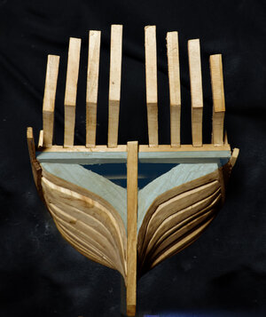
the hull planking takes a drastic bend and twist as they meet the stern so if there is no solid backing for the planks they tend to go flat.
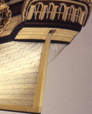
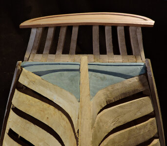
on this model you can see filler transom pieces added to the stern
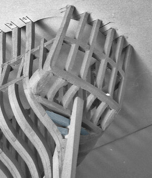
On the Tecumseth there is no way of knowing what was done at this section of the hull so what i did was add a lower transom and filler piece. The edge of the upper transom where the stern timbers are set into has a beveled edge for the ends of the hull planks. It was cutting this bevel when the knife slipped and i cut my thumb.
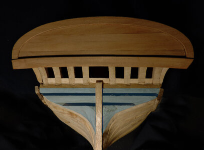
On some ships there is a molding between the hull planking and transom planking like this model has.
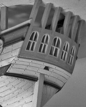
There is nothing on the wreck that can confirm if there was a lower molding or not, but it is drawn on the original plan.
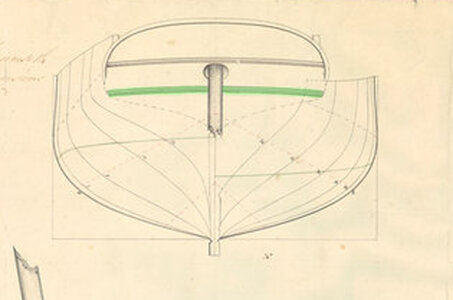
That molding will sit in the green tinted area and it will also lock in the foot of the stern timbers.
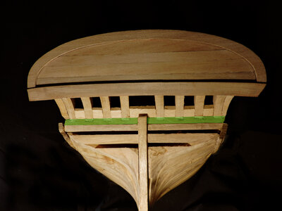
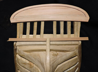
The Tecumseth was built as a basic ship for the purpose of an armed transport so nothing fancy was done no figurehead, no scroll work at the stern just your basic ship. So with that in mind the lower molding may of been nothing but a simple molding or it could have a molded edge like you see on the Halifax example. When i take a close look at the high resolution drawing it kind of shows a modeled edge.
I will take the two pieces shown in the picture and cut a molded edge on them.

the hull planking takes a drastic bend and twist as they meet the stern so if there is no solid backing for the planks they tend to go flat.

on this model you can see filler transom pieces added to the stern

On the Tecumseth there is no way of knowing what was done at this section of the hull so what i did was add a lower transom and filler piece. The edge of the upper transom where the stern timbers are set into has a beveled edge for the ends of the hull planks. It was cutting this bevel when the knife slipped and i cut my thumb.


On some ships there is a molding between the hull planking and transom planking like this model has.

There is nothing on the wreck that can confirm if there was a lower molding or not, but it is drawn on the original plan.

That molding will sit in the green tinted area and it will also lock in the foot of the stern timbers.


The Tecumseth was built as a basic ship for the purpose of an armed transport so nothing fancy was done no figurehead, no scroll work at the stern just your basic ship. So with that in mind the lower molding may of been nothing but a simple molding or it could have a molded edge like you see on the Halifax example. When i take a close look at the high resolution drawing it kind of shows a modeled edge.
I will take the two pieces shown in the picture and cut a molded edge on them.
- Joined
- Dec 1, 2016
- Messages
- 5,128
- Points
- 728

one method for cutting moldings i have used this method with success and it workd great for 1:48 scale and less.
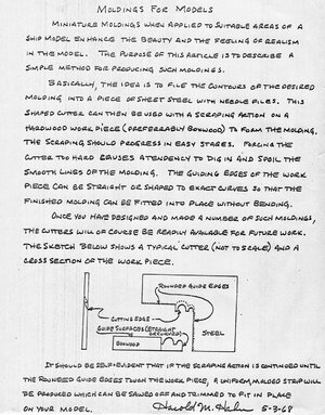
The Tecumseth is large scale 1:32 and this is the method i used described in the following illustrations.
Then i will follow up with the actual making of the molding.
starting with a pieces of pearwood 1/4 x 1/4
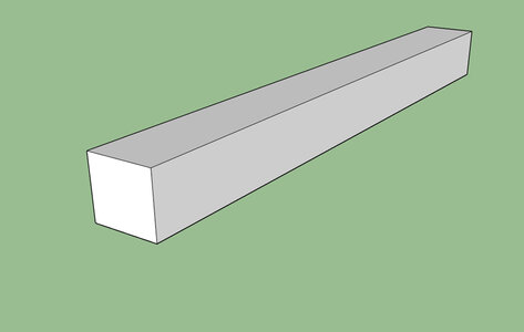
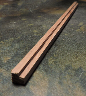
i set my 4 inch table saw and cut a grove
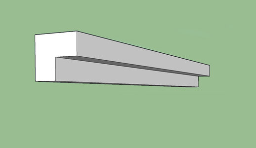
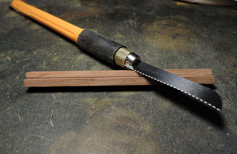
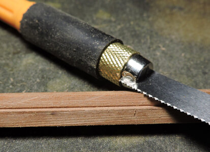
flipping the piece i used a razor saw and by hand cut a grove
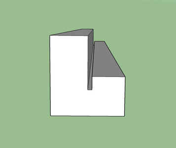
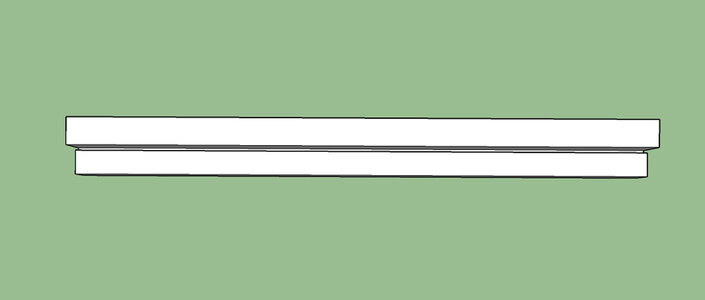
using files i rounded out the tops to produce the molded edges.
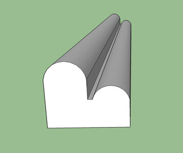
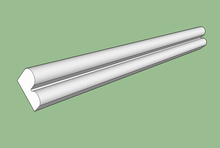
really simple

The Tecumseth is large scale 1:32 and this is the method i used described in the following illustrations.
Then i will follow up with the actual making of the molding.
starting with a pieces of pearwood 1/4 x 1/4

i set my 4 inch table saw and cut a grove

flipping the piece i used a razor saw and by hand cut a grove


using files i rounded out the tops to produce the molded edges.


really simple
- Joined
- Dec 1, 2016
- Messages
- 5,128
- Points
- 728

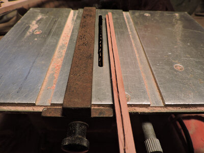
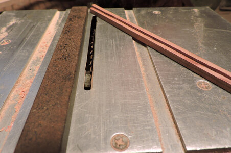
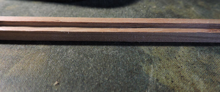
step 1
to cut the grove i used my 4 inch table saw and set the height of the blade and fence. I got a nice straight clean cut from my little Jarmac table saw. When i saw the $475.00 price tag on a 4 inch saw i went to Ebay and picked up the Jarmac for $45.00 and it serves the purpose. You can get a lot of 4 inch table saws for under a $100.00 to $200.00
These little hobby tools do come in handy for light, small work. Their only drawback is you need big tools to cut down lumber for the little tools to handle, or you have to purchase resawn wood. I admit there are junk tools and well built precision tools but for the average hobby model builder you can do just as well with a $40.00 saw than you can do with a $400.00 table saw.


- Joined
- Dec 1, 2016
- Messages
- 5,128
- Points
- 728

- Joined
- Dec 1, 2016
- Messages
- 5,128
- Points
- 728

once i have the grove cut in, from here on it is a matter of files to finish the molding
i have a set of needle files and some larger ones.
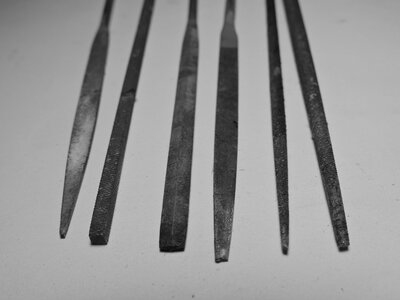
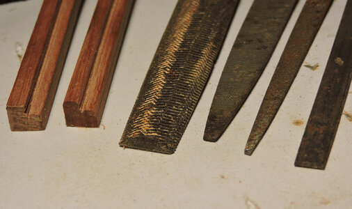
using the files i run them along the groves shaping and rounding out the edge of the molding.
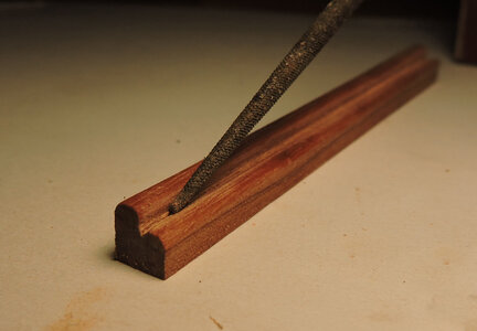
looking back on the 3D illustrations i file in the profile of the molding.
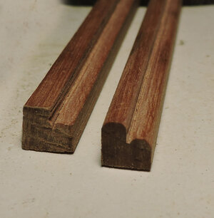
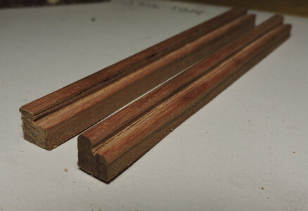
as i get closer to the finished molding i check it on the model for size.
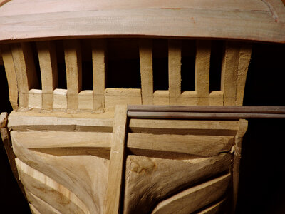
i have a set of needle files and some larger ones.


using the files i run them along the groves shaping and rounding out the edge of the molding.

looking back on the 3D illustrations i file in the profile of the molding.


as i get closer to the finished molding i check it on the model for size.

Last edited:
- Joined
- Dec 1, 2016
- Messages
- 5,128
- Points
- 728

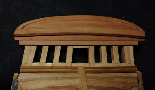
planking up the stern
the lower molding is now installed and it is just a matter of planking up the lower section of the stern.
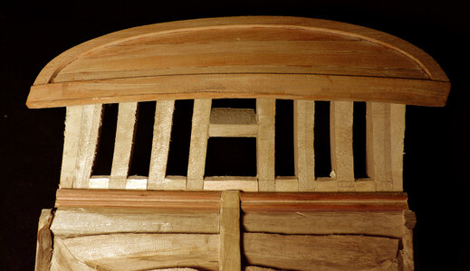
i started with a wide plank at the top because it has an arc to it
next plank under the top arched one, i am running the planks long so i can trim them when the planking is done.
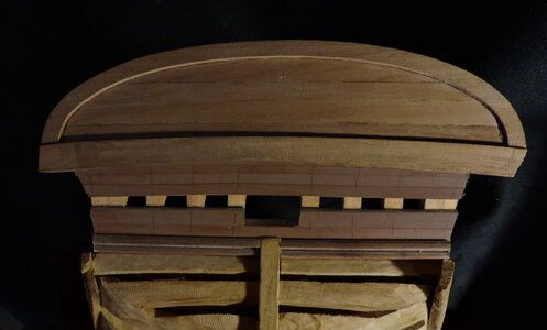
one by one each plank is fit in. i realized when i looked at the top i forgot to mark the stern timbers for nails so i marked the timbers as i planked the bottom section.
planking the stern was an easy straight forward job.
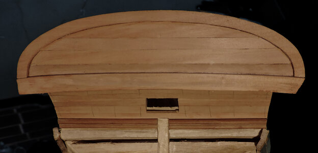
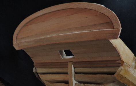
the lower molding is now installed and it is just a matter of planking up the lower section of the stern.

i started with a wide plank at the top because it has an arc to it

next plank under the top arched one, i am running the planks long so i can trim them when the planking is done.

one by one each plank is fit in. i realized when i looked at the top i forgot to mark the stern timbers for nails so i marked the timbers as i planked the bottom section.

planking the stern was an easy straight forward job.


- Joined
- Dec 1, 2016
- Messages
- 5,128
- Points
- 728

the next job is to plank the sides of the hull but before i can start that i need to make another molding.
At one point i stop using the plans and the reason is "the hand of man" even if you follow the plans as close as you can get there will always be a slight difference in thickness of the wood, a slight difference in assembly of parts, and what you built is not dead on exactly as per the plans because all those tiny little differences add up. So i am now using the model itself to make patterns. The use of plans were used for the overall size and shape of the ship all the fit and finish is now done using what is termed "relative scale and pattern. In other words parts are now fabricated to fit the model and not necessarily what was draw.
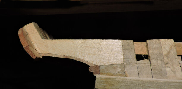
there is a molding that goes from the top of the wales to the inside planking of the stern.
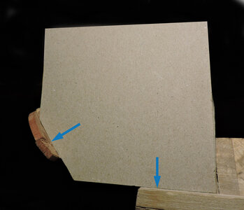
i need to know what the angle is at the blue arrows and just as i suspected they are just a pinch different than the drawing.
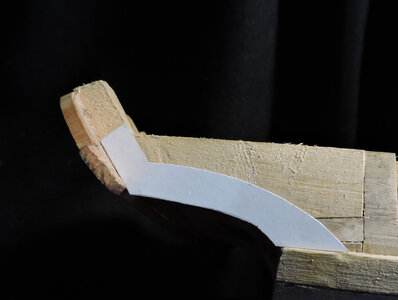
next i will draw the shape of the molding This is drawn on the plans which indicate there should be a molding here and suggest the shape. The drawn pattern is not exactly as the plans but close enough.
At one point i stop using the plans and the reason is "the hand of man" even if you follow the plans as close as you can get there will always be a slight difference in thickness of the wood, a slight difference in assembly of parts, and what you built is not dead on exactly as per the plans because all those tiny little differences add up. So i am now using the model itself to make patterns. The use of plans were used for the overall size and shape of the ship all the fit and finish is now done using what is termed "relative scale and pattern. In other words parts are now fabricated to fit the model and not necessarily what was draw.

there is a molding that goes from the top of the wales to the inside planking of the stern.

i need to know what the angle is at the blue arrows and just as i suspected they are just a pinch different than the drawing.

next i will draw the shape of the molding This is drawn on the plans which indicate there should be a molding here and suggest the shape. The drawn pattern is not exactly as the plans but close enough.
- Joined
- Dec 1, 2016
- Messages
- 5,128
- Points
- 728

i never knew there was such a thing until a friend of mine gave me a few boards of the stuff and i fell in love with it.
MACHINABLE TOOLING FOAM

 www.generalplastics.com
when i carve something i use a block of the foam to practice on or as you can see i use it for pattern making.
this is the area i will be working on but i am not sure what i am doing so i did a foam mockup
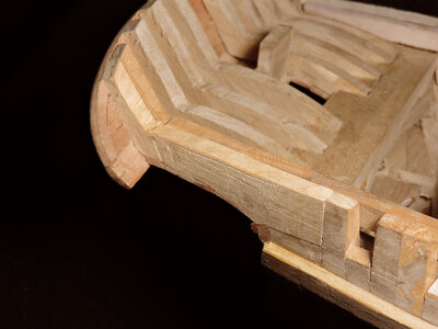
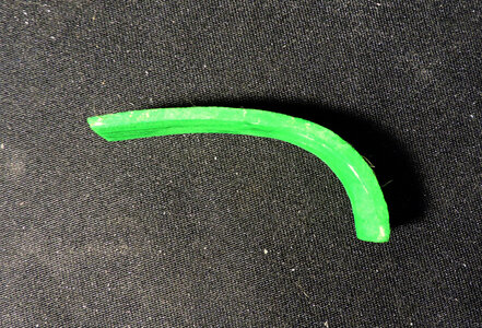
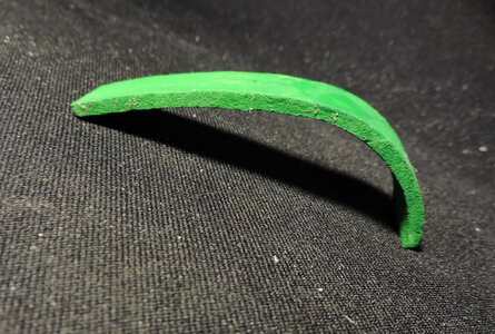
i cut the pieces out of the foam board and painted them bright green so they show up.
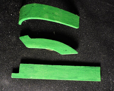
first piece i used the cardboard pattern and cut out the side stern molding
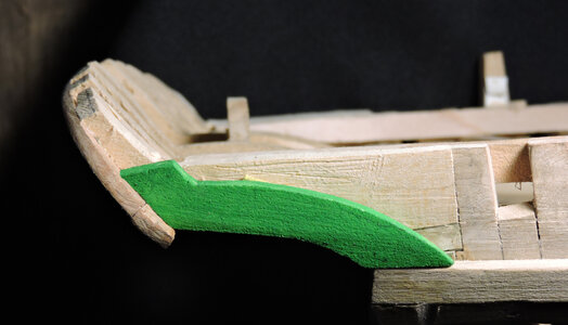
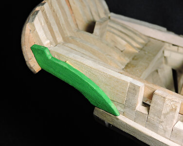
second piece is the cover board that runs the length of the hull and sits on top of the frames and waterway.
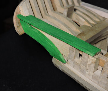
between the side molding and the coverboard will be planked in.
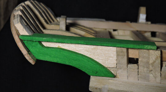
MACHINABLE TOOLING FOAM

Tooling and Molds
Our tooling foam boards are ideal for master models, check fixtures, rapid prototypes, mold and foundry patterns, and composite tooling. Get LAST-A-FOAM® here!
when i carve something i use a block of the foam to practice on or as you can see i use it for pattern making.
this is the area i will be working on but i am not sure what i am doing so i did a foam mockup

i cut the pieces out of the foam board and painted them bright green so they show up.

first piece i used the cardboard pattern and cut out the side stern molding


second piece is the cover board that runs the length of the hull and sits on top of the frames and waterway.

between the side molding and the coverboard will be planked in.

- Joined
- Dec 1, 2016
- Messages
- 5,128
- Points
- 728

- Joined
- Dec 1, 2016
- Messages
- 5,128
- Points
- 728

There is a molding that caps the stern timbers, it is a tricky piece to make because looking at this drawing from the stern it has an arc from side to side with a tight bend going down at the sides. The to the right looking at it from the top view the stern has an arcfrom front to back. The cap molding is bending in two directions.
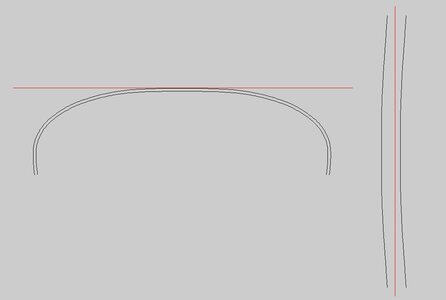
a view of the mockup
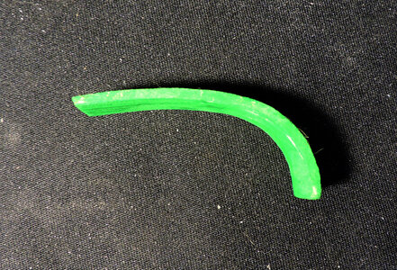
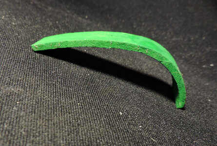
This cap molding fots on top of the stern timbers and ends at the lower stern molding
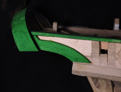
here is my problem
first don't pay any attention to the piece of clay on the right it is there just to hold the cap in place.
from the last stern timber there is nothing to fasten the end of the molding to, it is just hanging there. Now there is the molding that runs around the top of the stern but it is only a thin piece and not enough to actually attach the molding cap to.
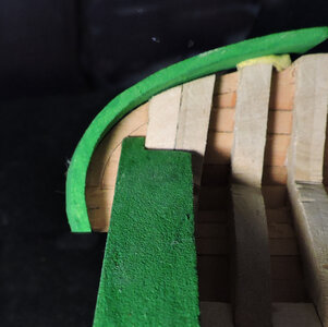

a view of the mockup


This cap molding fots on top of the stern timbers and ends at the lower stern molding

here is my problem
first don't pay any attention to the piece of clay on the right it is there just to hold the cap in place.
from the last stern timber there is nothing to fasten the end of the molding to, it is just hanging there. Now there is the molding that runs around the top of the stern but it is only a thin piece and not enough to actually attach the molding cap to.

Last edited:
- Joined
- Dec 1, 2016
- Messages
- 5,128
- Points
- 728

one idea i came up with is to reshape the side molding
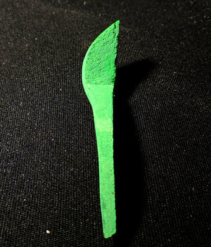
when i fit it to the hull it filles the area behing the stern planking
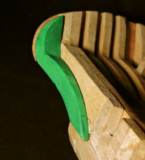
now there is a solid wood backing to fasten the cap molding to
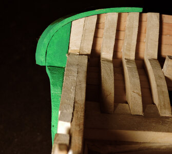
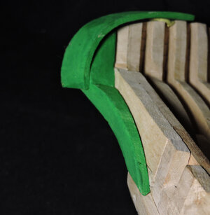
Although this seems to solve the problem it just does not feel right because it is such a large piece of timber.
taking a look at the replica Tecumseth the builders avaoided this question by changing the stern.
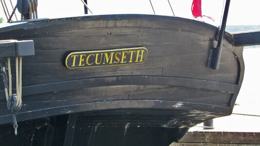
the cap molding stops short of going around and down the stern
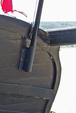
it is clear the cap molding stopped at the timbers at the side.
Another thought was bending this cap molding in two directions and the extreme bend as the molding goes around the side of the stern. Here it was laminated.
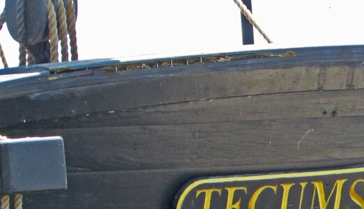
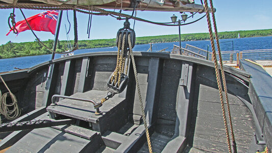
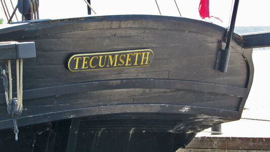

when i fit it to the hull it filles the area behing the stern planking

now there is a solid wood backing to fasten the cap molding to


Although this seems to solve the problem it just does not feel right because it is such a large piece of timber.
taking a look at the replica Tecumseth the builders avaoided this question by changing the stern.

the cap molding stops short of going around and down the stern

it is clear the cap molding stopped at the timbers at the side.
Another thought was bending this cap molding in two directions and the extreme bend as the molding goes around the side of the stern. Here it was laminated.


- Joined
- Dec 1, 2016
- Messages
- 5,128
- Points
- 728

on the General Hunter the cap molding blends into the side molding but on the Tecumseth it just did not work out that way
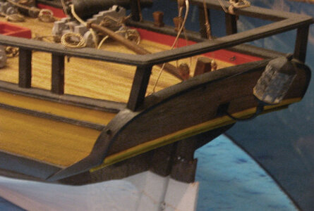
so here i am stuck and not sure what to do
i searched all the stern images i have looked through model gallery on this and another forum and really did not find an answer so if anyone has an idea i sure would like to hear from you

so here i am stuck and not sure what to do
i searched all the stern images i have looked through model gallery on this and another forum and really did not find an answer so if anyone has an idea i sure would like to hear from you
- Joined
- Dec 1, 2016
- Messages
- 5,128
- Points
- 728

ok then
no one has an image, drawing or anything showing sterns that extend beyond the side of the hull?
i will have to just take a guess at it
no one has an image, drawing or anything showing sterns that extend beyond the side of the hull?
i will have to just take a guess at it


