Sovereign of the Seas, a reconstruction

Hallo Waldemar, can you name the source of the so-called Newton manuscript from the second quarter of the 17th century? The paper is often mentioned, but always without a source.

Thank you very much
Stephan
 
Hallo Waldemar, can you name the source of the so-called Newton manuscript from the second quarter of the 17th century? The paper is often mentioned, but always without a source.

Thank you very much
Stephan
Hi Stephan,

It was published in Mariners Mirror in 1994.
On the web still available.
 
As we have seen in the previous post projecting the center on top the Lely painting the wider top timber / less tumble home of Dean & Bushnell seems to fit the picture better then the smaller top timber width of the 1620 treatise.
The Newton manuscript however mentions a top timber width reaching from the smaller 1620 treatise value towards the larger Dean values or between 2/3 bm to 4/5 bm for SotS this is between 31' to 37' 2".

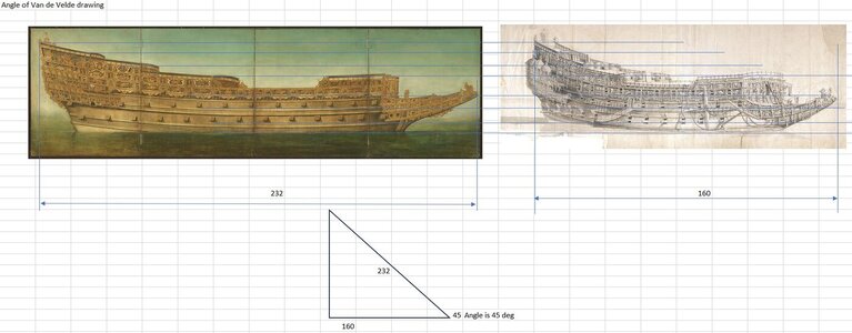
To counter check the Lely painting wider top timber width I will compare it with the measured width in the Van de Velde Morgan drawing. However the Morgan drawing is made at an angle and I first have to determine the angle.

To do this I have scaled the morgan drawing to the Boston drawing in height reference points.
I also have put both drawings on top of each other in Fusion to scale the Van de Velde drawing to the Boston drawing.

After that I measured both drawing over the same horizontal reference points. The Boston drawing is 232 ft, the Morgan drawing +/-160 ft.
Dividing these gives nearly the square root of 2 which means the ship is drawn at a nearly 45 deg angle.

Van de velde angle.jpg

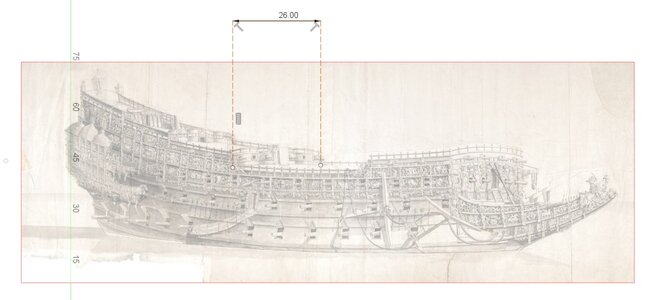
With this I can measure the width of the top timber on the main deck.

Top timber width van de Velde.jpg
Measuring around 26' at a 45 deg angle or 1,41 x 26 = 36'9" and very close to the wider deck of the Newton manuscript and the Dean value.
It seems or Pett design had a wide top timber design which seems reasonable to make space for the upper gun decks. Petts larger frame radius above the bm also acknowledges this.

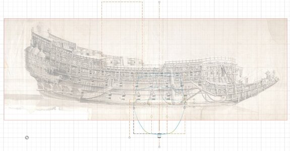
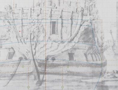
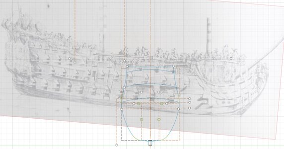
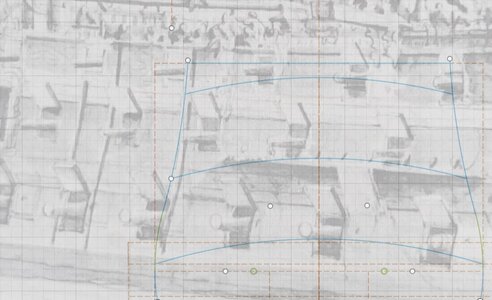
So I have redrawn the center frame using the larger Dean/Newton document top timber width, reconstructed the decks using data handed over from the navy archives and plotted the frame at a 45 deg angle on top of the Morgan drawing.
center frame reconstruction van de Velde with Newton max top timber.jpg

Te data seems to be very close. The decks do fit, the gun ports fit, the waterline fits, the angle of the lower gun ports is very close. It only looks the angle of the gun ports on the second gun deck are too much upright allthough the entrance port is again pretty close.

Sofar I wil go for the wider top timber/ deck space as mentioned in the Newton manuscript, in Dean and Bushnell.
Maybe I will retest a smaller radius for the top timber sweep to get a closer fit for the second gun deck port angle. Also I will make a comparison on the other Van de Velde drawings of the ship to double check the comparison, but that will be next time.
 
Last edited:
As we have seen in the previous post projecting the center on top the Lely painting the wider top timber / less tumble home of Dean & Bushnell seems to fit the picture better then the smaller top timber width of the 1620 treatise.
The Newton manuscript however mentions a top timber width reaching from the smaller 1620 treatise value towards the larger Dean values or between 2/3 bm to 4/5 bm for SotS this is between 31' to 37' 2".

To counter check the Lely painting wider top timber width I will compare it with the measured width in the Van de Velde Morgan drawing. However the Morgan drawing is made at an angle and I first have to determine the angle.

To do this I have scaled the morgan drawing to the Boston drawing in height reference points.
I also have put both drawings on top of each other in Fusion to scale the Van de Velde drawing to the Boston drawing.

After that I measured both drawing over the same horizontal reference points. The Boston drawing is 232 ft, the Morgan drawing +/-160 ft.
Dividing these gives nearly the square root of 2 which means the ship is drawn at a nearly 45 deg angle.

View attachment 432852

With this I can measure the width of the top timber on the main deck.

View attachment 432851
Measuring around 26' at a 45 deg angle or 1,41 x 26 = 36'9" and very close to the wider deck of the Newton manuscript and the Dean value.
It seems or Pett design had a wide top timber design which seems reasonable to make space for the upper gun decks. Petts larger frame radius above the bm also acknowledges this.

So I have redrawn the center frame using the larger Dean/Newton document top timber width, reconstructed the decks using data handed over from the navy archives and plotted the frame at a 45 deg angle on top of the Morgan drawing.
View attachment 432850

Te data seems to be very close. The decks do fit, the gun ports fit, the waterline fits, the angle of the lower gun ports is very close. It only looks the angle of the gun ports on the second gun deck are too much upright allthough the entrance port is again pretty close.

Sofar I wil go for the wider top timber/ deck space as mentioned in the Newton manuscript, in Dean and Bushnell.
Maybe I will retest a smaller radius for the top timber sweep to get a closer fit for the second gun deck port angle. Also I will make a comparison on the other Van de Velde drawings of the ship to double check the comparison, but that will be next time.
Old drawings, new 3D and basic math, you make a nice combination of them, Maarten.
Regards, Peter
 
The last check on the top timber shape and width I do with two additional Van de Velde drawings.

First a sketch made after the first rebuild when she received a more modern shorter beakhead. The open side galleries were removed and you can see the top cabin seems to be removed, allthough some other Van de Velde drawings contradict that.
I use this drawing as she clearly shows the rails along the side of the hull midships which highlight the shape of the top timbers.
This drawing is made at a 49 deg angle measured from the drawing scaled to the pther drawings in Fusion 360.
I projected my centre frame at this 49 deg angle and directly put it next to the rail along the hull.
center frame reconstruction van de Velde first rebuild with Newton max top timber.jpg

If I zoom in to the rail I think my current frame is again pretty close.
center frame reconstruction van de Velde first rebuild with Newton max top timber detail.jpg

The last acknowledgement is based on a Van de Velde drawing after the last rebuild in the 1680s.
Just at her launch from the yard looking at her from a 7 deg angle.
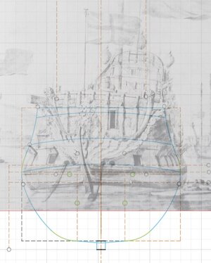
Again the frame seems to be a fit.
center frame reconstruction van de Velde last rebuild with Newton max top timber.jpg

And when zoomed in.
center frame reconstruction van de Velde last rebuild with Newton max top timber DETAIL.jpg

To me this acknowledges the proper centre frame design which fullfills a path between the contemporary documentation from two anonymus sources to Bushnell and Dean.

For this center frame I will start with preparing the rest of the hull.
 
This is a fascinating study in reverse-engineering, Maarten. I love all versions of the Sovereign, but the first re-build Sovereign is my favorite.
Hi Marc,

The rebuild sovereign is certainly interesting but there is not a lot of data of her regarding ornamentation. This as we only have sketches of her without any clearly drawn carvings.
So the original SotS is best documented to build a model from.
 
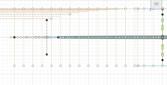
Line of greatest breadth top view

Work continues on the SotS.
Over the last months I have been reading all the available manuscripts and also @Waldemar very interesting blog of the O3 model. https://shipsofscale.com/sosforums/threads/naseby-1655-reverse-engineering-the-ship-model.11841/
The O3 model as made by Francis Sheldon in the late 1650's to solicitate at the Swedish court to become the new navy shipwright.
The very interesting about Francis Sheldon is that he was an apprentice of Peter Pett who actually build the SotS. Closer we can't get to his work then this.
In his blog Waldemar also compares the O3 model to the ratios of the hms Naseby or later Royal Charles, being a very close fit in ratios at a different scale. The original HMS Naseby was build by Peter Pett and Francis Sheldon working for Peter Pett on this build.

I compared the center frame of the O3 model to the lower part of the SotS center frame and these are pretty close in design. I will post this comparison later.

This gave me the idea to create a hull for SotS based on the ratios as given for the O3 model and see what the result is.

I will try to explain as much as possible the steps of how to create a hull from the provided data.

To start with the line of greatest breadth.
The line of greatest breadth is exactly what is says and showing the greatest breadth of the ship along the hull. This is a 3d shape with a top view and a side view together creating a 3d line.

Today the top view aft side of this line.
As the blog of Waldemar shows on the O3 model this top view aft is created by a mezzoluna transformation. This is not a simple arc but an arc with a constant changing radius.

To create this mezzoluna I first have to determine the timber and space on my ship.
The timber and space is the thickness of the frame and the space between the frames which was normally the same as te thickness of a frame in a war ship.
From the center frame at 1/3 of the keel from the front or 2/3 from the stern I can place 34 frames towards the stern from the center frame.
This is 2/3 x 127 foot = 84 2/3 foot / 34 = 2 1/2 foot timber and space. This means my floors will be 1 1/4 foot thick.

So I have to devide my complete ship in parts of 2 1/2 foot of which I want to draw every third frame in full scale.
You can see that below.


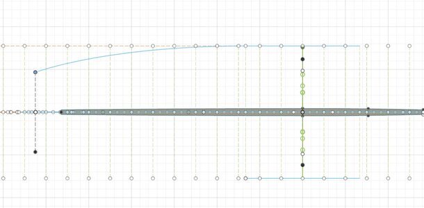
The midship section of the top view line of greatest breadth on the O3 model is straight over 8 frames for the center and aft of the center frame. So I start with a straight line over 8 frames from center frame towards the stern.
Mezza luna transformation 4.jpg

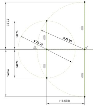
To create the mezzoluna you draw half a circle behind the ship with the same breadth as the hull. For the SotS this is 46,5 ft or a radius if 23,25 ft.
Mezza luna transformation 1.jpg
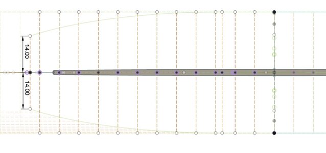
In this half circle you have to draw the width of the transome, the widest point of the hull in the stern. For SotS this is 28 ft.
I draw a circle of 14ft radius to cross the half circle at its center line. My transome is now set.
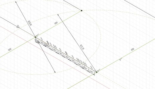
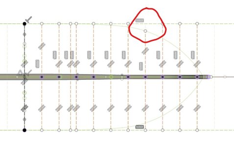
Now I have to devide the space between the transome and the center line of the half circle by the number of frames I want to draw proportionally to the frames in the aft end of the ship.
Mezza luna transformation 2.jpg

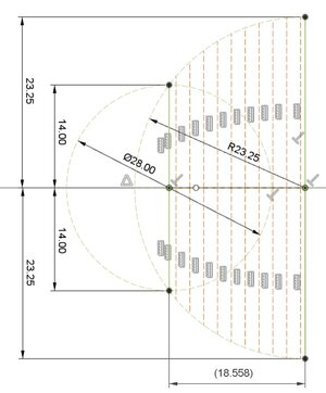
For these points I draw vertical lines to cross the circle. The crossing of the circle determines the breadth of the ship at that specific frame.
Mezza luna transformation 3.jpg

By drawing horizontal lines towards the corresponding frames I create the shape of the hull at maximum breadth for the top view.
Mezza luna transformation 4 (1).jpg

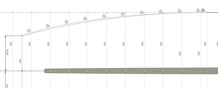
Now these created points can be connected with each other by using tangent arc lines, every tangent arc line has a slightly different radius.
Mezza luna transformation 5.jpg

What is the difference with a regular arc you can see below. The mezzoluna in blue, the single arc in green.
Mezza luna transformation vs tangent arc (green).jpg

The mezzoluna creates a wider hull towards the stern creating more bouyancy in the stern of the ship.

Next time the fwd part of the line of greatest breadth.
 
Last edited:
Work continues on the SotS.
Over the last months I have been reading all the available manuscripts and also @Waldemar very interesting blog of the O3 model. https://shipsofscale.com/sosforums/threads/naseby-1655-reverse-engineering-the-ship-model.11841/
The O3 model as made by Francis Sheldon in the late 1650's to solicitate at the Swedish court to become the new navy shipwright.
The very interesting about Francis Sheldon is that he was an apprentice of Peter Pett who actually build the SotS. Closer we can't get to his work then this.
In his blog Waldemar also compares the O3 model to the ratios of the hms Naseby or later Royal Charles, being a very close fit in ratios at a different scale. The original HMS Naseby was build by Peter Pett and Francis Sheldon working for Peter Pett on this build.

I compared the center frame of the O3 model to the lower part of the SotS center frame and these are pretty close in design. I will post this comparison later.

This gave me the idea to create a hull for SotS based on the ratios as given for the O3 model and see what the result is.

I will try to explain as much as possible the steps of how to create a hull from the provided data.

To start with the line of greatest breadth.
The line of greatest breadth is exactly what is says and showing the greatest breadth of the ship along the hull. This is a 3d shape with a top view and a side view together creating a 3d line.

Today the top view aft side of this line.
As the blog of Waldemar shows on the O3 model this top view aft is created by a mezzoluna transformation. This is not a simple arc but an arc with a constant changing radius.

To create this mezzoluna I first have to determine the timber and space on my ship.
The timber and space is the thickness of the frame and the space between the frames which was normally the same as te thickness of a frame in a war ship.
From the center frame at 1/3 of the keel from the front or 2/3 from the stern I can place 34 frames towards the stern from the center frame.
This is 2/3 x 127 foot = 84 2/3 foot / 34 = 2 1/2 foot timber and space. This means my floors will be 1 1/4 foot thick.

So I have to devide my complete ship in parts of 2 1/2 foot of which I want to draw every third frame in full scale.
You can see that below.


The midship section of the top view line of greatest breadth on the O3 model is straight over 8 frames for the center and aft of the center frame. So I start with a straight line over 8 frames from center frame towards the stern.
View attachment 446477

To create the mezzoluna you draw half a circle behind the ship with the same breadth as the hull. For the SotS this is 46,5 ft or a radius if 23,25 ft.
View attachment 446474
In this half circle you have to draw the width of the transome, the widest point of the hull in the stern. For SotS this is 28 ft.
I draw a circle of 14ft radius to cross the half circle at its center line. My transome is now set.
Now I have to devide the space between the transome and the center line of the half circle by the number of frames I want to draw proportionally to the frames in the aft end of the ship.
View attachment 446479

For these points I draw vertical lines to cross the circle. The crossing of the circle determines the breadth of the ship at that specific frame.
View attachment 446478

By drawing horizontal lines towards the corresponding frames I create the shape of the hull at maximum breadth for the top view.
View attachment 446473

Now these created points can be connected with each other by using tangent arc lines, every tangent arc line has a slightly different radius.
View attachment 446476

What is the difference with a regular arc you can see below. The mezzoluna in blue, the single arc in green.
View attachment 446475

The mezzoluna creates a wider hull towards the stern creating more bouyancy in the stern of the ship.

Next time the fwd part of the line of greatest breadth.
An interesting post, Maarten. I'm curious about the 1st perspective prints.
Regards, Peter
 
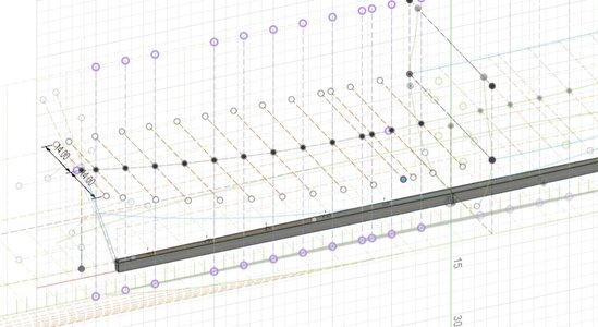
Line of greatest breadth side view.

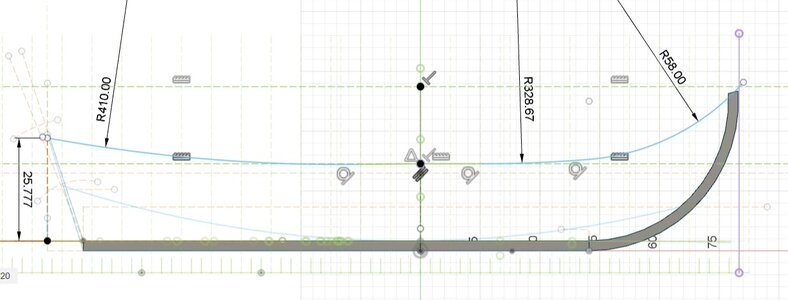
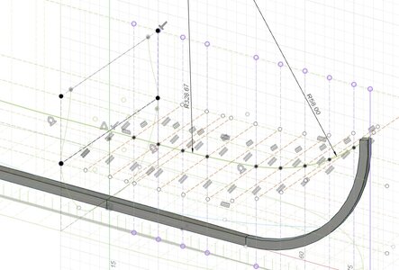
To create the perspective line of the greatest breadth the next step is to draw the side view of the line of greatest breadth.
This line is created from two curves and a straight line in the ships center.
The straight line is drawn over the first 6 frames fwd and 6 frames aft.
For the fwd part of the hull the line is created from 2 curves devided in two equal pieces.
Before the center frame there are 31 frames. 6 are used for the straight line. 25 remain the first arc over 13 frames, the second over 12 frames.
The end point of this line should end at the 31st frame in longitudinale direction and at double depth in height.
The radius of the first arc is 17 x depth = 17 x 19.333 = 328,67 ft
The second arc is determined by a tangent arc between the first arc and the end point.
Creating a second arc with radius 58 ft.

Drawing these creates the line below.
Line of greatest breadth side view.jpg

The line towards the aft is a single arc towards the point of greatest breadth in the stern being the transome at a height of 4/3 x depth or 4/3 x 19.333 = 25,777. Creating a radius of 410 ft.

The side view of greatest breadth is now drawn.
Next time combining both to a 3d line and view.
 
Martin, I'm very impressed. For me, these are Bohemian villages, which makes them all the more interesting to me. Simply great.
Hi Tobias,

Hope you enjoy it and get some inspiration to look into it yourselve.

That was it to me as well before looking into it, and most probably a large part still is.
But it is very interesting to work with it, srarting to understand the influence of these lines on the shape of the vessel.

I can only recommend to look into it and you will be suprized how quickly it will become more clear to you.
 
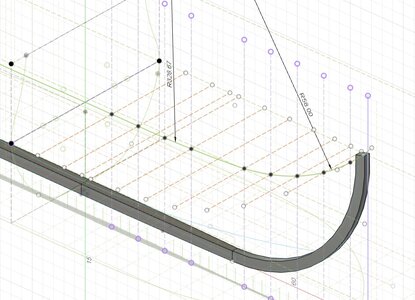
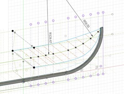
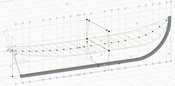
I have drawn a top view and a side view line of greatest breadth and combining these two create the 3d line of greatest breadth.

To do this I first draw horizontal lines in 3d view to the side view line of greatest breadth at the maximum breadth of 46,5 ft or 23,25 ft to both sides. You do this for every frame you want to draw. For me this is every 3rd frame.
Line of greatest breadth fwd 3d 1.jpg

If this is done you switch to the top view and match the drawn horizontal lines to fit with the top view line of greatest breadth.
Line of greatest breadth fwd 3d 2.jpg

If this is done for all the lines and you switch to 3d view you see the shape already.
Line of greatest breadth fwd 3d 3.jpg

Now the ends of the vertical lines are connected with each other. I wanted to do that with arcs but fusion 360 doesn't want to do that in 3d, so I used straight lines, for creating my frames this is not an issue.
You now see the fwd line of greatest breadth.
Line of greatest breadth fwd 3d 4.jpg

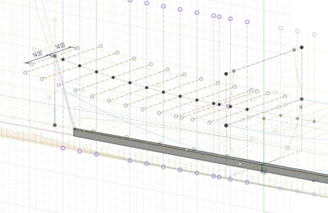
For the aft the process is the same as can be seen below.
Line of greatest breadth aft 3d 1.jpg
Line of greatest breadth aft 3d 2.jpg
Line of greatest breadth aft 3d 3.jpg

Resulting in a complete line of greatest breadth.
Line of greatest breadth aft 3d Sheldon.jpg

Next will be the line of the floor.
 
Does Fusion has a 3D spline? I tried to draw something similiar with Rhino, but find it rally difficult. I can easier work with the profile view,

Perhaps I should give this another try.
Hi Christian,

I am on a steep learning curve in Fusion 360 ROTF, but it seems to have a 3D spline possibility (just Googled) which I will look into to draw tangent curves in 3D plain.
At least I can draw in 3D plain with straight lines connecting the points created in two 2D view drawings as I did above.

If I figured it out I will let you know.
 
Last edited:
Back
Top