Samuel 1650 – a Dutch mid-17th century trader

Joined
Apr 26, 2023
Messages
383
Points
323

Location
European Union
.​
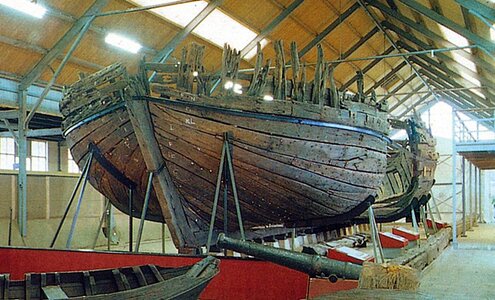
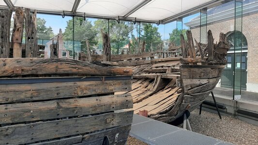
Persuaded by Ab Hoving and assisted by Maarten by pointing out the archaeological documentation, I undertook the reverse engineering of the important shipwreck E81 – Samuel 1650, excavated in the Ijsselmeer basin in the north of the Netherlands. The wreck is complete enough to allow analysis of the entire underwater part of the hull.


Shipwreck E81 - Samuel 1650 - Jan Rypma.jpg
Shipwreck E81 (Samuel 1650), photo by Jan Rypma


* * *​

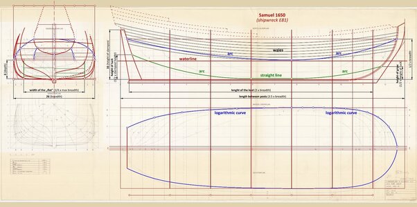
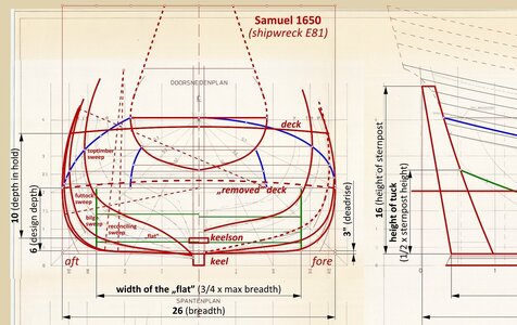
The very small deadrise (only 3 inches), the supernatural width of the "flat" (3/4 of the maximum hull breadth instead of the typical 2/3), the tight bilge sweep (radius of only 1/6 of the maximum hull breadth as opposed to the 1/4 typical for warships), and above all the extremely low design depth, and consequently draft (not to be confused with depth in hold; only 1/15 of the hull length between posts instead of the typical 1/10 for ocean-going ships), clearly betray the ship's purpose as a coaster, i.e. a coastal and inland freighter with the ability to enter the shallowest ports, but not coping very well with open, deep water navigation.

Other vessel proportions are already quite typical and their values are indicated in the accompanying diagram.


ViewCapture20240305_014311.jpg


Due to its proportionally shallow draft, the ship had to be leewardly, but this sailing negative property was partly compensated for by a sharp gripe, i.e. bow entry, formed by the keel-stempost assembly, as well as a relatively sharp run.

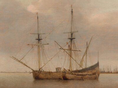
The character of this ship is perhaps best conveyed by the vessel shown in the below mid-17th century painting by Abraham de Verwer, except that Samuel 1650 appears to have had a beakhead and a square tuck stern.


Verwer Abraham de - View of Hoorn, c. 1650 - Copy.jpg

.​
 
Thanks for your observations and conclusions, Waldemar, which are interesting and revealing as always.
I also like the De Verver picture you show here, which depicts a 100 feet long fluit, accompanied by a 70 feet long wijdschip, but indeed the shapes of Samuel and this fluit must not have deviated very much. It shows daily workhorses, like there must have been thousands, hardly adorned with a multitude of carvings, large flags and supplied with a host of cannons. We model builders sometimes seem to forget that reality is not always as fancy as we show in our models. What we see here is reality without romance, and yet the picture is so full of atmosphere...
But that was of course not the purpose of your post. Sorry for my intrusion. :)
 
.​
Thank you very much, Ab, for your warm comment. And no, you never bother, quite the opposite. How did you guess that exactly this painting by de Verwer made such an impression on me? :)

* * *​

Now I would also like to show, using this particular case as an example, how important it is to carry out this kind of analysis on the basis of original 'first-hand' data rather than already interpreted, indirect material.

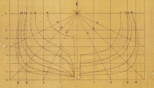
The following excerpt from the graphic archaeological documentation shows two sets of cross-sections of the E81 shipwreck. The dashed lines indicate the cross-sections as taken directly from the excavated wreck, while the contours drawn with the solid line are the result of subsequent „correction” of the wreck's hull shapes using smoothing diagonals and waterlines.

However, It must be stressed that such proceedings are altogether unsuitable in this context, as these graphical par excellence smoothing methods were not yet in use during this period, in particular because they would have also required drawing complete designs on paper, which was likewise not yet practised at the time, at least not universally. As can be seen, the result of such inappropriate treatments can be a significant deformation of the actual shapes, with the result that the data after such „corrections”, while being perfectly enough to build a model, is practically no longer suitable for the analysis of the design methods of that very period.


original - interpretation.jpg

.​
 
Last edited:
Thank you Waldemar for this explication.
There is one thing that still puzzles me. Shipbuilding theory and actually building a ship are different matters. Somewhere between making the design for a newly ordered ship (no matter if it was done on paper, wax, a slate or whatever it takes) and the purchasing of the appropriate pieces of curved wood (be it actually selected in a wood or at a dealer's yard) there must have been a moment that both were connected by the making of some molds or templates to select the right curves of naturally grown wood. One for the bilge futtock, one for the second futtock and probably one for the top timbers as well. I am convinced that one of each will do, because I have seen in model building practice that most of these shapes hardly change over the length of the ship.
Can you give me an idea how this process must have been carried out? How can the sketchy, downscaled main frame be turned into a full size template? My imagination comes to a complete halt here. Perhaps you can shed some light on this matter.
 
Hi Waldemar, Ab,

Very interesting to see, again maximum breadth is here very close to the waterline and at ships center even at the waterline.
Also the line of maximum breadth is not following the sheer of the wales.
Building the ship would we expect the "scheerstrook" would be mounted following the line of maximum breadth or follow the line between the two lower wales?
 
.​
Very interesting to see, again maximum breadth is here very close to the waterline and at ships center even at the waterline.
Also the line of maximum breadth is not following the sheer of the wales.
Building the ship would we expect the "scheerstrook" would be mounted following the line of maximum breadth or follow the line between the two lower wales?

Hello Maarten,

Technically it is a bit simpler for me to address the issues you have raised, so in that order...

To my understanding, a sheerstrake (scheerstrook/scheergang) is precisely nothing more than the physical equivalent of the geometric line of the greatest breadth of the hull. Actually, it probably cannot be otherwise, since in the Dutch/North Continental context of the way ships are built, it is the geometrical basis for the correct positioning of frame timbers, both below and above the sheerstrake. In fact, I cannot even imagine how the hull could be correctly shaped in this method in any other way, i.e. without this fundamental design line.

A separate issue is the parallelism or otherwise of the wales to the sheerstrake. Indeed, in the vast majority of cases that I am aware of, the wales followed the sheerstrake line and, for example, in the fluit description by Rålamb in his 1691 work it is stated expressis verbis that the sheerstrake coincides with the top edge of the second wale from below. However, there are examples, such as this one (i.e. Samuel 1650), that an orthodox adherence to this rule(?) would simply not allow for a logical geometrical construction and at the same time consistent with the archaeological material, and this is true for both ends of the hull. I believe that, in this particular case, this is a deliberate design feature closely related to the inland character of this vessel:

Given its proportions, especially its shallow draft, the Samuel 1650 can almost be compared to a virtually non-turning raft, i.e. a vessel with very high hydrostatic stiffness, all the more so if we still take into account the cargo located low in the hull, as opposed to the heavy armament placed high, always above the waterline level on armed ships. As a result, in this particular case, the line of greatest breadth meeting the waterline in the midship region is even beneficial, as it at least slightly laterally 'softens' an unnecessarily and even detrimentally ultra-stiff ship, as such excessive stiffness is downright harmful to the ships' masts and rigging.

.​
 
.​
Can you give me an idea how this process must have been carried out? How can the sketchy, downscaled main frame be turned into a full size template?


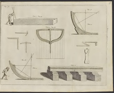
First, it is probably worth using an example of tracing the stempost taken from van Yk's 1697 work, which demonstrates that geometric design methods were indeed used.


Pages from Yk Cornelis van - De nederlandsche scheeps-bouw-konst open gestelt - 1697.jpg

In the description to the engraving above, on page 58, there is a thorough explanation of how to obtain the circular curve of a stempost, knowing in advance the height and rake of the stempost; the final shape of the arc of the stempost being obtained with a compass. This could have been a normal compass for drawings made to scale, or a string compass for real scale tracing.

Indeed, as you point out, in many cases it would have been inconvenient or even impossible to use a radius and a compass. Particularly in such cases, the designer could easily measure on the drawing (or calculate mathematically if he was proficient in calculations) the so-called deflection arrow. After scaling it to the actual scale, he could use this value when collecting timbers, for making a working templates or for giving instructions to carpenters. To give a simple example: we want to buy 52 timbers with a length of 9 feet and a deflection (in the middle) of 1 foot.

In this way, the two approaches, the geometric and the practical, combine and complement each other in a harmonious, even essential way.

Regarding the curvature of the individual frame sections, I could distinguish two basic types of the frame shapes in the Dutch/ North Continental tradition:

1) futtock sweeps with a fixed radius, bilge sweeps with a fixed radius (especially for dedicated freighters sporting frames of boxy contours),
2) futtock sweeps with variable radius, bilge sweeps with fixed radius (for more demanding hull shapes, for example for warships; Samuel 1650 also belongs to this type),
3) only futtock sweeps with variable radius, without bilge sweeps (in the Dutch context I have not yet encountered this form, but this simplified shape was promoted by William Sutherland in his 1711 work, and also used in at least one design of English origin from the first decades of the 18th century).

Of course, the conversion of the frame arcs defined geometrically (i.e. mainly by means of the radius) to a method more convenient in practical application (using the chord of the arc and the desired deflection) was just as possible as for the stempost case described above.

It can also be added that, given the enormous routine and scale of shipbuilding, designing, converting and making templates each time, especially for almost identical ships, would indeed have been an unnecessary waste of time and energy. It was perhaps more efficient to keep and re-use the existing designs and templates already made once.

.​
 
Thx Waldemar,

For this ship you see a depth to breadth ratio of
1 : 4 1/3, is that towards the shallow limit for a sea going vessel of this size? Is she still within a default rule of thumb?

If the wreck is the Samuel than this is a ship trading between Spain and Northern Europe, this as the Samuel came from Allicante before she sank at Urk.
 
.​
For this ship you see a depth to breadth ratio of 1 : 4 1/3, is that towards the shallow limit for a sea going vessel of this size? Is she still within a default rule of thumb?

If the wreck is the Samuel than this is a ship trading between Spain and Northern Europe, this as the Samuel came from Allicante before she sank at Urk.

Hmm..., I'm not sure it's possible to precisely quantify proportions and shapes for ships with different purposes, as judgements are subjective, conditions are variable over time, and there's a rather complicated relationship of dozens of different parameters involved. As I am able to assess the Samuel 1650, she was designed to enter any port, even the shallowest, but at the same time features were given to her so that she had good enough seaworthiness to sail from port to port in open waters.

Of course, the contradictions can't quite be reconciled, so if I were the crew of Samuel 1650, I wouldn't stray too far into open water in case of very bad weather and the need to hide in some sheltered spot (and the Bay of Biscay can indeed be very nasty storm-wise), yet at the same time I would take great care to avoid as much as possible the leeward shore.

In short, getting the set of diverse (usually conflicting) constraints and design parameters right is certainly the domain of experience and good design sense, which is not easy, if at all possible, to put into some kind of table.

.​
 
The measurements of the ship I received from the Archaeological Agency were: 93 x 26 x 10. That means that the ship was a little bit wider and a little bit deeper than the formulae suggest. What are the measurements (and especially those of the depth) you found Waldemar? The ratio for depth and width should be 1 : 2,5. A diversion from 2,5 to 4,3 must have had serious consequences for the seaworthiness of the ship (see our conversation about the Wasa dimensions).
 
.​
Ah, I was yet to do a fine-tuning of this diagram, but let's try it now with what is ready.


ViewCapture20240307_113811.jpg


In fact, everything is correct, and it all depends on how we measure and assess this vessel. The Archaeological Agency correctly reported a depth of 10 feet measured in the conventional ('utilitarian') way, i.e. from keelson to the deck level (depth in hold).

In contrast, from the point of view of shaping the hull form, for me the design height (i.e. from deadrise level to maximum breadth level) is even more important, especially as this design depth is also closely related to the draft level, taken into account while designing ships. And the decks, in essence, could have been built at 'any' height and in that sense (i.e. shaping the hull form) their height is of course also taken into account, but to a lesser extent (or maybe better: in a different way).

In addition, it just so happens that on Samuel 1650, due to her low proportions, the first, lowest deck was not built (I have marked this „removed” deck with a dashed line in the diagram). This unbuilt deck, on a ship of normal proportions, would usually be placed at about sheerstrake level or slightly higher. My guess is that the absence of this lowest, unbuilt deck is, in this particular case, closely related to the convenience of use and the capacity of the ship's hold – it was simply unnecessary, if not in the way.


I'll take this opportunity to give a couple of the dimensions I've read from the archaeological record:

Main dimensions

Breadth:
26 feet
Keel length: 78 feet (3 x breadth)
Length between posts: 91 feet (3.5 x breadth)
Design depth: 6 feet
Depth in hold: 10 feet

Dimensions of master frame components:

Deadrise:
3 inches
Width of the „flat”: 19½ (3/4 x breadth)
Futtock sweep: variable radius (1/2 x respective breadth)
Bilge sweep: 4 1/3 (fixed radius; 1/6 x max. breadth)
Reconciling sweep: 17 1/3 (fixed radius; 2/3 x max. breadth) [?]
Toptimber sweep: variable radius (3/2 x half-breadth) [?]

.​
 
Last edited:
.​
Something is fishy here...


Not necessarily, it's the same problem that, incidentally, occurs on 'millions' of other ships with sides coming together (ie. featuring tumblehome).

Personally, I would solve this structural problem by not fitting all the frame timbers before laying the deck (to leave gaps in the side to slide the deck beams in from the side), and only fit those missing frame timbers in the next stage.

.​
 
.​
Besides, in the upper parts of the hull, this problem may not even exist at all due to the rather large gaps between the frame elements.

.​
 
.​
Still another solution would be to leave a little slack, by shortening the deck beam slightly (I estimate that even about one inch would be enough) so that it can be mounted from below. That is, by inserting it deeper into the hull lengthwise, and then lifting it while rotating it to a transverse position.

.​
 
But it is not in accordance with any description we have of the building proces. Why take such unusual measurements for such a humble, everyday vessel? Much easier to place the widest point at the location of the deck, like both Witsen and Van Yk describe.
Witsen explicitly describes how the beams of the upper deck were inserted: First the beams were placed on top of some sort of scaffolding, and only then the deck clamp was applied. But the lower deck needed the dovetails to keep the sides together.
Can mistakes in measuring be the cause? Looking at the first picture of this thread, a clear tumblehome is not visible as far as I can judge.
But who am I?
 
Last edited:
.​
Why take such unusual measurements for such a humble, everyday vessel? Much easier to place the widest point at the location of the deck, like both Witsen and Van Yk describe.

On pages 70 and 71 of van Yk's work there are a couple of examples from which it is very clear that the level of greatest breadth does not coincide with the height of the deck, and the distance may be quite large (more precisely with the upper level of depth in hold, which can be considered the same). I have not searched further, but I am absolutely sure that one would find many more such dimensional specifications in both van Yk's and Witsen's work.

Witsen explicitly describes how the beams of the upper deck were inserted: First the beams were placed on top of some sort of scaffolding, and only then the deck clamp was applied.

Ab, you have just given another way to deal with the problem of placing deck beams in hulls sporting tumblehome, confirmed in written sources. I was sure it was just an artificial problem.

Can mistakes in measuring be the cause? Looking at the first picture of this thread, a clear tumblehome is not visible as far as I can judge.

Agreed, but this observation only applies to the toptimbers located at the very bow of the ship, since the curvature, or rather the inclination of these very fore toptimbers must, as they approach the stempost, increasingly align with the inclination of the stempost, which in this case is outwards. However, still on the first bend, just above the gripe (specifically above the junction of the keel with the stempost), the toptimbers are still inclined inwards, as they are throughout the rest of the hull, going astern, forming a tumblehome.

I am still attaching below the excellent photo kindly supplied yesterday by Maarten, which shows this phenomenon quite well. The forwardmost toptimbers are sloping outwards like a stempost, and all the others are sloping inwards, forming a tumblehome.


20190727_130633.jpg


Naturally, I cannot know the exact rationale of the designer of the Samuel 1650 in not placing the line of greatest breadth five feet higher, but I can guess that for the following reasons, among others:

– it was unnecessary for the increase in draught, since the draught was, after all, intended to remain small,
– it would even have been detrimental, as it would have had the effect of increasing the lateral stiffness of the hull, already excessive,
– it would have virtually eliminated the tumblehome, which was considered beneficial at the time (e.g. it was thought to give the ship better resistance to wind and waves, to make it more difficult to board merchantmen, etc.; see, for example, Georges Fournier's Hydrographie 1643 on this).

.​
 
It is sad and exciting at the same time that archaeological finds finds don't seem to fit the theoretical descriptions. :)
Robbed of my foundations I give up believing literature...

In the mean time: of the five contracts mentioned on page 70/71 none had a depth below 1/10 of the length:
a ship 154 x 38 x 17,3
a ship 155 x 36 x 17
a fluitschip 140 x 34,3 x 16,6
a spiegelschip 85 x 22 x 11
a hooker 72 x 18 x 10
I don't see any references of lower laid decks.
 
Last edited:
.​
But no! Ab! Please! If it weren't for the literature (meaning period written material), and before that your exquisite interpretation of Witsen's work, which I started with by the way, we wouldn't even have a clue how to interpret these wrecks. One perfectly complements the other, but the basis is precisely the literature...

.​
 
Back
Top