Le Fleuron 1729 - 64 Gun Ship PoB Scratch Build in 1:48 - (Ancre Monograph-J. Boudriot/G. Delacroix)

Thank you all.
WOW!! Looks fabulous. Ken. I like the first one (boxwood), and then pear. However, the boxwood version looks a bit wider, maybe because of the contrast. But boxwood would be my first choice. The real question is will there be more boxwood elements in the stern?
Thanks Jim. You have a good eye. The Boxwood set of rings IS just slightly wider. The is because I broke 2 sets of rings prior to the finial set you see. So I didn't push sanding them down any further, even with 400grit.
Good morning Ken, very nice work. I would agree with Jim and think the boxwood version is the nicest. As Jim has also pointed out the stern of the Le Fleuron has a lot of carving and then it should all fit together.

View attachment 406431

If you have a mill I would use that to taper it. Here is a picture of how I did it for the rudder, for example.

View attachment 406432
Tobias, thanks. I was hoping for someone to offer alternatives to my first thought/approach. My thought was basically the same as you illustrate, using a board where you use your mill's table and raising it on one end to shave 50% of the piece, then flipping it over and repeating the process. However, I think I will use your method as it is clear now to me it would offer much better control of the stem and more accurate removal of material. Thumbsup :)

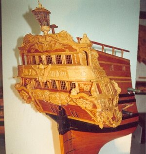
As to the decorative elements, I have more work to do. To your point, there are a LOT of carvings on the stern of the ship. The photo of Le Fleuron's stern/galleries is a grand example. Note the underlying wood is a lighter version of Pear, so the contrast is not that great between it and the carvings planking underneath. I should state now, I'm either going to keep that planking with the same Pear I used in the stem OR use Black Hornbeam, which I would tie (appearance) to the wales and stem, which will have black elements. The contrast shown in the photo you provided is nice. Below are a couple of photos showing too great a contrast for my liking, although they are beautiful examples of talented modelers. I understand this is a choice and beauty is in the eye of the beholder. :D;)
1470941726.jpgLe Fleuron_15.jpg
I will do some further testing. Again, as you stated, there is a LOT of decorative carvings on the stern. I want to be sure the Boxwood test piece I used was not representative of all the Boxwood I have in stock. Hoping the wood I do have is of better quality and easier to work with.
wNice update. Looks real good. And keep the dog away.
Thanks Stephan. I can't even believe you brought up the dog. Don't jinx me!!! ROTF
Very nice stem. I must confess I am colorblind but I agree, keep the contrast of the rings to a minimum.
Thanks Herman. Sometimes I wish I was color blind.ROTF
Hi Ken. That looks very good indeed. I’m impressed with your work and your determination to get it as perfect as you can, also including your thought process within your log adds interest. I wouldn’t even attempt a project as complex, this level of build is beyond me for many reasons but I do enjoy following others in their endeavours. It’s a beautiful subject, perhaps the promised version from Modelship Dockyard could be the way for me to go, I could probably manage Le Fleuron from a kit.
Thank you Ken. I've learned so much here on SoS and adopted many sources and methods of those who share. I do try and share my thought process, not just to share back, but to test it with those with much deeper knowledge than I possess. I hope they will point out any existing flaws in my thought process and approach and prevent me from making the mistakes others have who have gone before me. I try and emulate them as much as I can.;)Thumbsup

The stem looks fantastic Ken!
Thank you much Paul. And again for your help with supplier information you were kind enough to share with me! ;)
Wonderful work on that stem Ken, I admire your tenacious approach to “getting it right”. I think the other Ken said it well in his prior post. Lots of good how to’s in your log. I also enjoyed reading your rationale for the different methods of caulking too. The graphite and PVA solution is something I’ll put away in my mental filing cabinet.
Thank you much Roger. I try and share things, as many others do, mostly to show what works and what doesn't, from my perspective, of course. I find sharing my mistakes and how I corrected them have the most value to others. If I can point out a hole, maybe someone else won't twist their ankle! ROTF This hobby of ours has humbled me in many ways. In good ways.
 
Hello Mates!

When I last posted, I needed to reduce my beakhead aft to fore and keel to top of the beakhead. Tobias shared a proven method using his mill, to perform the same job with a rudder. I decided to use the same approach.

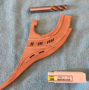
To the head shaking of some machinists somewhere, I have found that collets and/or even a chuck are sufficient to hold end mills fast when working with small pieces of wood stock. :rolleyes: A tool holder, while providing a much more secure connection it is overkill IMO and slows down the change process. But, for this job I wanted to use the largest 4 flute end mill I had due to the beakhead piece's construction. I can't afford to have some small end mill catching on the recessed insert and splintering the edge. So I will use a 1/2", 4 flute end mill.

To show the size, you can see it in relation to the beakhead.
thumbnail (12).jpg


The thing is even I know you can't find a collet or a drill chuck that will accommodate 1/2" AND fit my Sherline mill.

So while I wait for a 1/2" tool holder from Sherline, I decided to rebuild the stern that was broken.

Basically, the only things that survived from the original were the wing transom, helms port and an 2 inner counter pieces.

Both sets of outer counter timbers were replaced. I replaced circular open and decorative portals, this time out of Boxwood. All of the cross timber pieces are new. The upper and lower sills of the gunner's room gun ports were added. The lower are not part of the plan, but needed in this "shell" construction. And finally, I added the inner window frames.

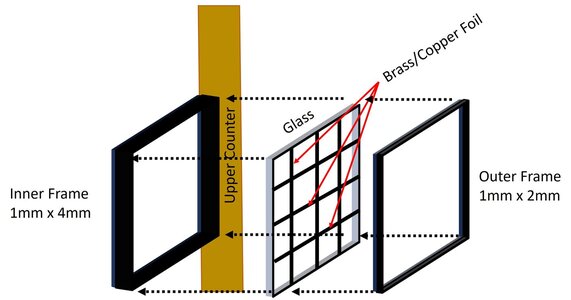
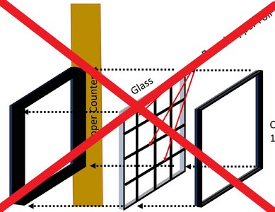
I will not construct windows as they were on the real ship. My skills are not quite there. I will attempt to present a realistic representation. The drawing below should be enough to illustrate my approach.
Stern Gallery Window Assembly.jpg

I'm going to use slide covers for microscopes for the window panes themselves. Conveniently, they measure 22mmX22mm and my widest window is 20.5. :D

For the window pane dividers I've orders both brass and copper foil, brass in 0.02mm thickness,

coper in 0.05mm thickness.

The copper has conductive properties so I know I can blacken it. The brass is yet to be determined. Both thicknesses will be easy to cut to the correct dimensions.

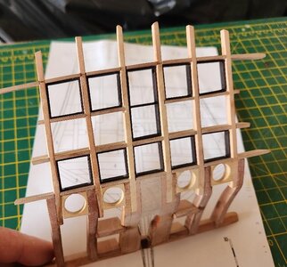
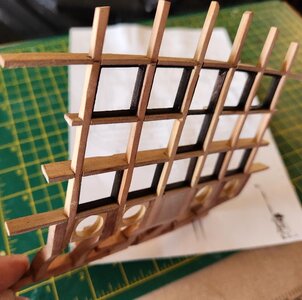
The photos below show the new stern piece with the window's inner frames in place. The frames are dry fitted themselves at the moment. The small CA deposits in the inner corners adhere the frame pieces to themselves, but not to the counter timbers.

thumbnail (11).jpgwith window sills.jpgthumbnail (9).jpg

Final sanding will be done once the windows are installed.

I'm ok with progress to date, although there are a couple of things I've logged into my brain to address next time around. The structure is very strong. I think if my puppy tried to chew this version 2.0 she may have to see the Vet with a tooth ache! ROTF

As always, thanks for following along, for your comments and likes and most importantly, your generosity in sharing your knowledge to help me out. Special thanks this time goes to Tobias. Well maybe I'll wait to see how the beakhead comes out!...j/k.ROTF

Till next time...
 
Last edited:
When I last posted, I needed to reduce my beakhead aft to fore and keel to top of the beakhead. Tobias shared a proven method using his mill, to perform the same job with a rudder. I decided to use the same approach.
Ken, here on the forum someone has already shared the technology for narrowing the crown. We take a board (or plywood), lay down double-sided tape, lay bars on the sides (marked with yellow lines) with the thickness of the thickest part of the workpiece, yours seems to be 6 mm (if I’m not mistaken). In the bow part (arrow) we place a block of the required thickness. Example: if you need to grind the nose down to 4 mm, then the first block will be 1 mm. Then we take sandpaper, glue it onto a block of wood and remove it along the side bars. Then we turn the nose over and put a 2 mm block in front (where the arrow is) and repeat the same steps with sandpaper. As a result, you will get a uniform narrowing of the entire workpiece towards the nose. I checked, the method works
 
Why oh, why you haven't posted this earlier. It would save me a lot of trouble. Great idea with those windows.
I'm not touching mine on side galleries, till you make yours;):)
Hi, @WojtasS. While I like to keep a positive outlook, please keep in mind my plan is theorycraft. :) It makes sense in my head. I can hope it plays out the way I hope. I will keep track of my steps, in case things work out as I hope. ;)
Smart to use microscope coverslips. I used them a lot in my study years. They are very thin and are made of real glass.
Your work looks great. And feed the dog properly.

Hey Stephan, thanks for the kind words. I already started to test the use of the microscope covers. The very thing that makes them great for a scale ship is as you stated, they are very thin. This also is the very thing that makes them difficult to trim, as recent tests have revealed. :rolleyes: I will continue to try some other methods. I wish I had one of those tools to bend photo etched brass. I would like to test it, but I'm not going to buy one just to test. Hmmm, although I could make a case I will need one to build a scratch ship oven at some point. :p.....or am I rationalizing?
Ken, here on the forum someone has already shared the technology for narrowing the crown. We take a board (or plywood), lay down double-sided tape, lay bars on the sides (marked with yellow lines) with the thickness of the thickest part of the workpiece, yours seems to be 6 mm (if I’m not mistaken). In the bow part (arrow) we place a block of the required thickness. Example: if you need to grind the nose down to 4 mm, then the first block will be 1 mm. Then we take sandpaper, glue it onto a block of wood and remove it along the side bars. Then we turn the nose over and put a 2 mm block in front (where the arrow is) and repeat the same steps with sandpaper. As a result, you will get a uniform narrowing of the entire workpiece towards the nose. I checked, the method works
Hi Sasha. I too vaguely remember this post. I will search for it when I get a chance. If I have some issues with the milling approach I will consider this. Thank you for taking the time to explain it in detail! Thumbsup:)
 
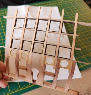
Just a quick update while still fresh in my thoughts. I wanted get an idea of the scale of the window panes I need to build. Frankly, I think I need smaller fingers! o_O But I guess this is why I have 12 pairs of tweezers. :rolleyes:ROTF

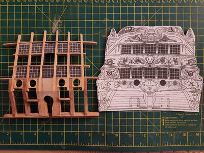
I printed out the decoration plan sheet on card stock, cut out the windows and placed them in my stern. They are ok, not super good. There are a few issues. The skilled eyes on the forum will notice them quite quickly. The most notable is the top cross member showing a greater curvature compared to the plan as seen in the space across the center 3 windows. With this stated, it does not affect any related structural geometry so I will leave it as is and have a glass of lemonade.:confused:

Note: The size and dimensional differences seen in the photo, I imagine, are due to a 3D structure and the flat 2D plan sheet. In person it actually looks quite good.

windows2(1).jpg
More to come soon....
 
Hi ken,

I agree with you here that this will be 3D vs 2D projection. As the real stern is tilted the curvature on the drawing will be less that it actually is.
 
Hello Everyone,
As always, thank you for your likes, comments and above all your input.

In the past, I've posted/shared every idea and approach I have had before I did the work. I've done this so that many of the more knowledgeable modelers might point out flaws in my thinking and I'd save some time making novice mistakes. Going forward, I'll not be posting my ideas unless they result in a successful solution. Saving me posting time and more importantly you guys from reading about an idea that never comes to fruition. ;)

I've had my head down working lately. As many know, many successes do not come without their failures.

So let me tell you about my last idea on the stern window fabrication...
Stern Gallery Window Assembly.jpg

Issues:
>It was impossible to process the brass/copper foil to the correct scale and to achieve a uniform result.
>The microscope slide covers were easily cut(I used one of those broken 0.6mm tungsten PCB drill bits that always break). However, being real glass it was impossible to "scuff" that transparent glass to achieve the translucent window pane I wanted. I might have been able to do so if I had a diamond honing plate, but I was not going to buy one for that sole purpose. Also, if you drop one of these, it's like dropping a contact lens. Get on your hands and knees!

Solution:
WAIT FOR IT.......construct windows the conventional way. :rolleyes:

Window Frames
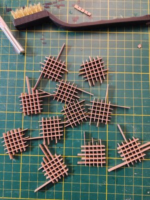
Selected the hardest Pearwood I had. I chose Pear once again as I wanted the window frames black and only had one block of Black Hornbeam. I would dye the Pear black. I constructed the frames using the same basic method I used for gratings. This was challenging as the windows have some tricky geometry, following the horizontal curvature of deck/cross beams as well as a slight vertical angle, which was less pronounced.​
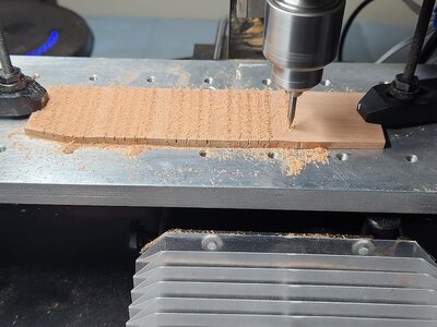
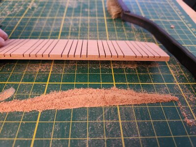
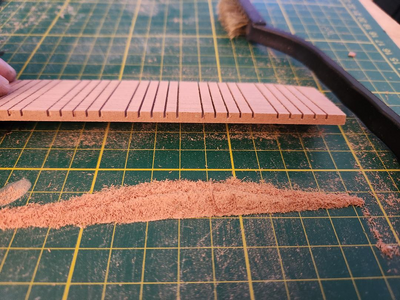
After a few unsatisfactory attempts, I settled on mill cutting 0.8mm slots 4.4mm, center on center to get the 4.0mm pane openings as in the plan.​
Important note: I wanted the length of each frame piece to follow the grain of the wood, for strength. Also, as a benefit, milling cross grain results in a cleaner cut.​
thumbnail (6).jpg


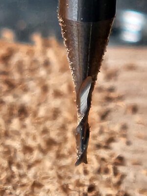
I was smart enough to bookmark an Allied Express link Jimsky provided some time ago. Picked up a set of 4X 0.8mm, 2 flute carbide end mills for $14. Sorry Jim, you do not get a commission! ROTF After some testing, I found this little beast had no issues cutting a 1.6mm deep cut in one pass at a feed rate of about 1.5mm/sec. o_O Other end mills I've used would take 3X 0.5mm passes at a slower feed rate if I didn't want the tool to break.
thumbnail (5).jpg

Great results. Extremely crisp cuts.

thumbnail (4).jpg
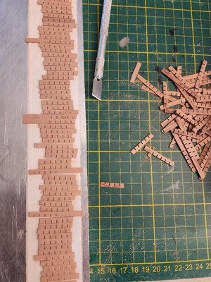
I then took each piece and cross cut (perpendicular to the milled slots), 0.95mm strips on the Byrnes table saw. I could have cut thinner if I had the zero tolerance blade plate.​
So my slots were 0.8mm and the pieces themselves were 0.95mm. They wont fit together as is so I needed to remove 0.15mm uniformly from ever piece. Onto a milled flat piece of aluminum with double sided tape and into the Byrnes thicknesser they went.​
thumbnail (3).jpgthumbnail.jpg
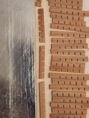
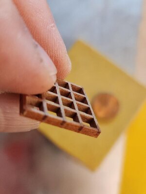
Assembly went smoothly, with 0.73mm (avg.) pieces fitting easily into 0.8mm slots. These did not result in a fit that was too loose at all and provided enough "play" to apply very slight pressure to achieve a progressive angle needed at the outer windows.​
Assembled, unprocessed.​
thumbnail (2).jpg
After rough processing.​
thumbnail (8).jpgthumbnail (7).jpg
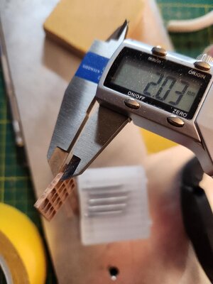
Final processing resulted in frames of 1.8mm thickness.​
Note:
Each frame was custom fit into its specific opening on the stern structure(unglued). Only then when the correct angle was achieved was each intersection glued. Usually if I use CA glue with wood it is Medium or Thick in some cases. For this application it was not possible to apply the glue to each slot and then fit the next piece. This would only result in a mess.​
Once the frame was assembled dry and held in place, thin CA was applied at each intersection. This worked very well as the capillary action sucked the glue into the smallest of gaps. I was able to remove the frame from the form 5 sec. after the last application.​
Window Glass
I went back to my favorite solution for scale glass, Mica. You can find this in processed sheets on eBay. Twenty USD will give you a supply for the rest of your modeling career.​
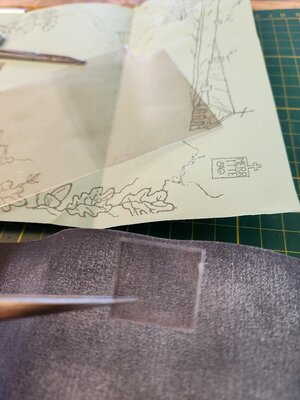
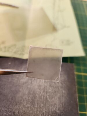
The Mica I have is completely transparent, with a very slight amber tint to it. It is flexible and easily cut with sharp scissors to any size.​
thumbnail (21).jpg
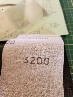
As I wanted translucent panes rather than transparent I lightly abraded each on some 3200grit micro mesh.​
thumbnail (20).jpg
thumbnail (18).jpg
As Mica is a mineral and formed in very thin micron thick layers it can be separated into thinner panes, if needed using a thin razor blade. Also, if handle too roughly the edges will separate slightly giving the panes a glazed look. I actually liked the effect.​
Assembled Stern Plate
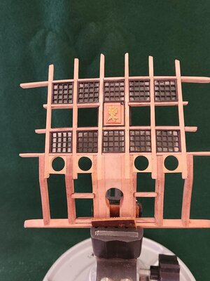
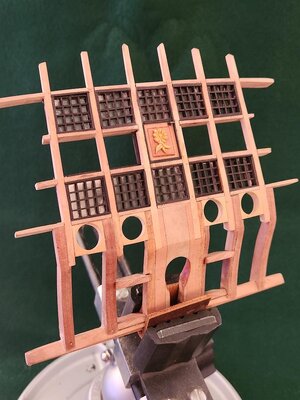
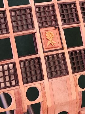
After dying the frames, they were fit into their respective openings. The following photos are of the stern plate in its current state. I one off created the door to the great cabin and added my own "floret" (fleuron) as decoration.
thumbnail (30).jpgthumbnail (27).jpgthumbnail (26).jpgthumbnail (30).jpg

Apologies for such a long post, but I wanted to keep all of the relevant work together. I went into each step for the windows as there were requests to show how I made them.

The last piece of the stern plate is the Taffrail, which is complete but was not added as I want to see how everything comes to fit on the ship.

On another note, there was some damage on the port side of the hull where the stern plate will be attached. I will need to come up with a solution to fix IT and also the starboard side in order to achieve balance, and find a more secure space for it. During this stern task session, I've been considering the entire project, from the hull's perspective. It would not be too late for me to scrap the shell and construct a fully conventional hull, with every frame. It is intriguing and frightening at the same time. I need some time to ponder...

Next Up
After a 2 week back order delay on my 1/2 inch tool holder it is in hand. I'll get ready to profile the beakhead. After that I will have to make some difficult decisions.

Once again, thank you all for following along. I appreciate the support and all of your comments and input. I truly value the critiques more than the compliments. Although pats on the back are always nice and the fuel for further motivation.

Till next time...
 
Wow!! I think we have yet another member as a candidate for writing his book, perhaps they (Ken and Paul) will both succeed in writing individual chapters to the same book about scale modeling! And, NO, I will not ask for commissions, from either of you but..., will ask to reserve a copy of the signed book.

I can echo, mon ami, Paul it is a great and ingenious tutorial. Many thanks! Thumbsup
 
Nice window gratings. For me, the more described the post, the better. I would never have thought that it was possible to make a window this way... grating on a milling machine is grating, and here you go... great work, thank you for your willingness to share @Hoss6262 . I can learn a lot. Beautiful.
 
Nice window gratings. For me, the more described the post, the better. I would never have thought that it was possible to make a window this way... grating on a milling machine is grating, and here you go... great work, thank you for your willingness to share @Hoss6262 . I can learn a lot. Beautiful.
@kuba91nt, Thanks. I'm glad it had some value to you. I will continue to share unique methods, but only if they have good results. ;)

Ken is using green mats ..... one more proof - just joking
Very very good work
and
many thanks for sharing the details of "How to do it" - very good tutorial
Thanks Uwek. I was thinking of buy 10 more green mats, like my buddy Stephan. :p They could improve my work results. But I forgot to put them on Santa's list. I can hear my Admiral now. "Why do you need TEN mats?!?" Does anyone have a good answer? ROTF
Thanks for this education in window making. I like the mica you used. A very nice looking result.
Thanks Stephan. I like the mica as it has an organic feel to it. I really need to work on my photography skills though. The mica shows some sort of glazing effect in the corners that is not really pronounced at all. The actual panes have a translucent, cloudy, not shiny look to them. The photos look like I spilled CA glue all over the place, which is not the case. I'll continue to work on my photography. ;)
Ken, quick question...how did you 'standardize' the spacing between cuts on the mill? Fixed number of turns of the wheel? Just measured and marked?
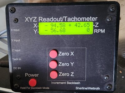
Along with Jim, I love this question Paul. I did not think of this point and hope the answer helps you and others. I can't imagine me wearing my reading glasses and putting my face 4 inches from a hand wheel to read it. One of the options Sherline mills have is DRO (Digital Read Out).

It tracks all 3 axis to 100ths of a mm. I chose Metric over Imperial. Both are available and can be order with a new mill or added as an upgrade to standard version.

It also provides a RPM readout. One of my favorite options is the Zero Out buttons. One press and your back to zero, very convenient! ;):D

So to answer your question. The plans show each small opening @ 4mm. I checked every window. The only deviation from 4mm was in the corners of the outer window complexes where the angle of the complex took the panes out of square. So it was EzPz.

Apologies if this is already known. From the perspective of the operator, X axis defines (width) Left to Right, Y axis, (depth) front to back.
So, if we know the panes need to be 4mm wide and high, then the inner measurement (between the cuts) needs to be the same. After the first cut, with the X axis zeroed out we turn the X wheel till the DRO reads the 4mm+diameter of the end mill, make the next pass, rinse and repeat. For this type of task, it is super easy. Most of the time invested is setting up. For this task the Y axis was not relevant.

thumbnail (32).jpg

The photo below shows the cuts making up 5 separate sets of window complexes, with 9mm space between them. I then separated each of the 5 and cut them into 0.9mm strips.
1702568323204.png

The cuts are exact in depth and width and I'm happy to say, may even be up to Paul standards. ROTF

The DRO functionality option, for me was a wise investment. I hope I answered your question clearly.
 
Back
Top