Kolderstok. Fluyt in oak

Update 6
We continued planking and got as far as the MDF struts could go.
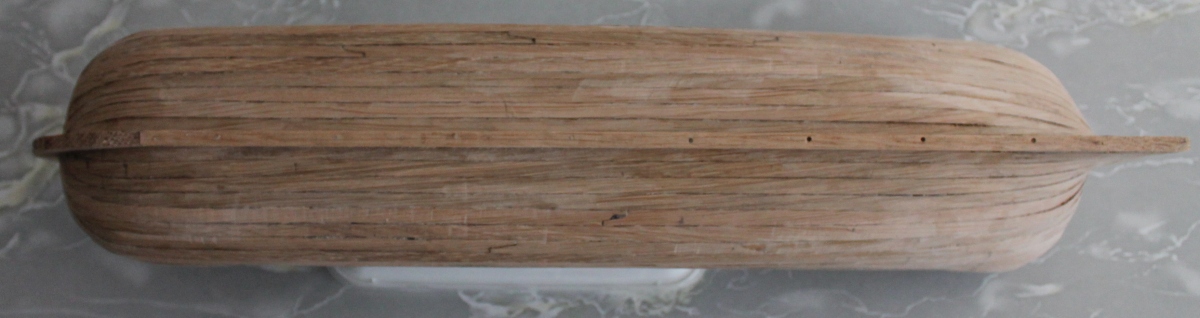
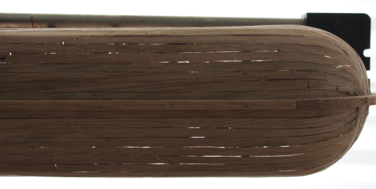
The bottom now looks like this:
06-1-Bodem.jpg


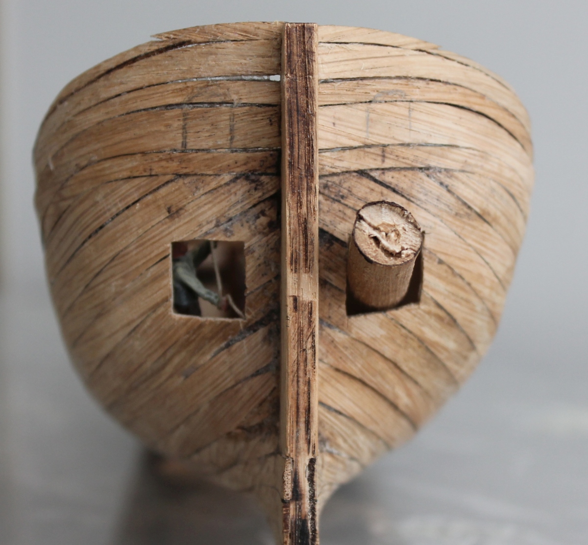
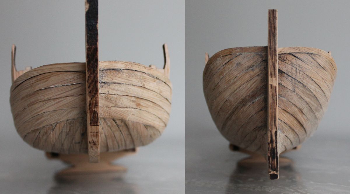
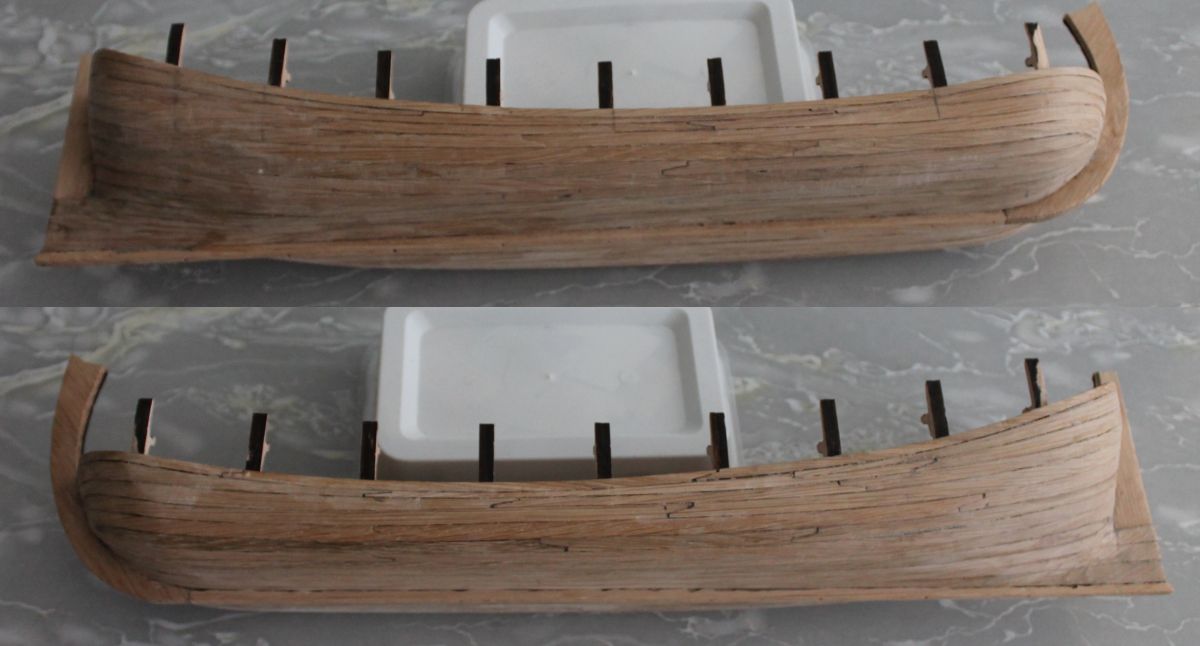
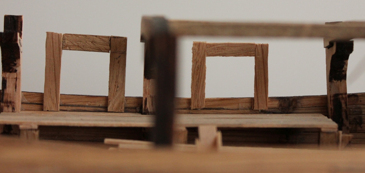
And the two stem ends like this:
06-2-BoegAchter.jpg


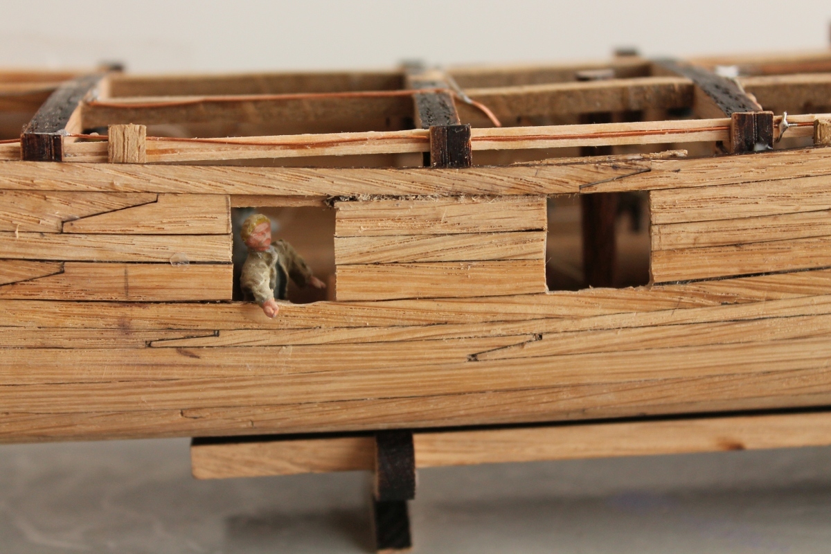
And these are the two sides:
06-4-Boorden.jpg


When you hold the whole thing up to the light, you see a ship you shouldn't sit in if you don't want to get wet. Fortunately, I'm not turning it into a sailing model.
06-5-Tegenlicht.jpg


I'm not going to do anything about this for now, from the outside you can see it. If it becomes visible with painting we'll see then.

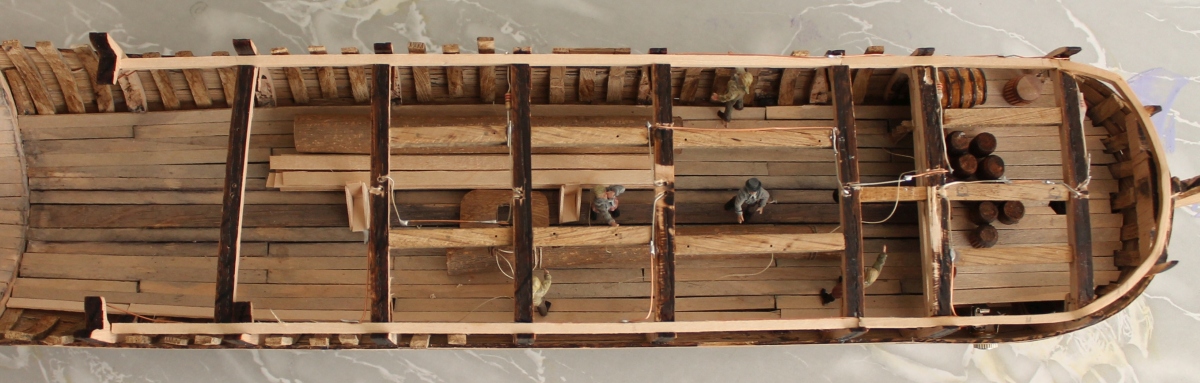
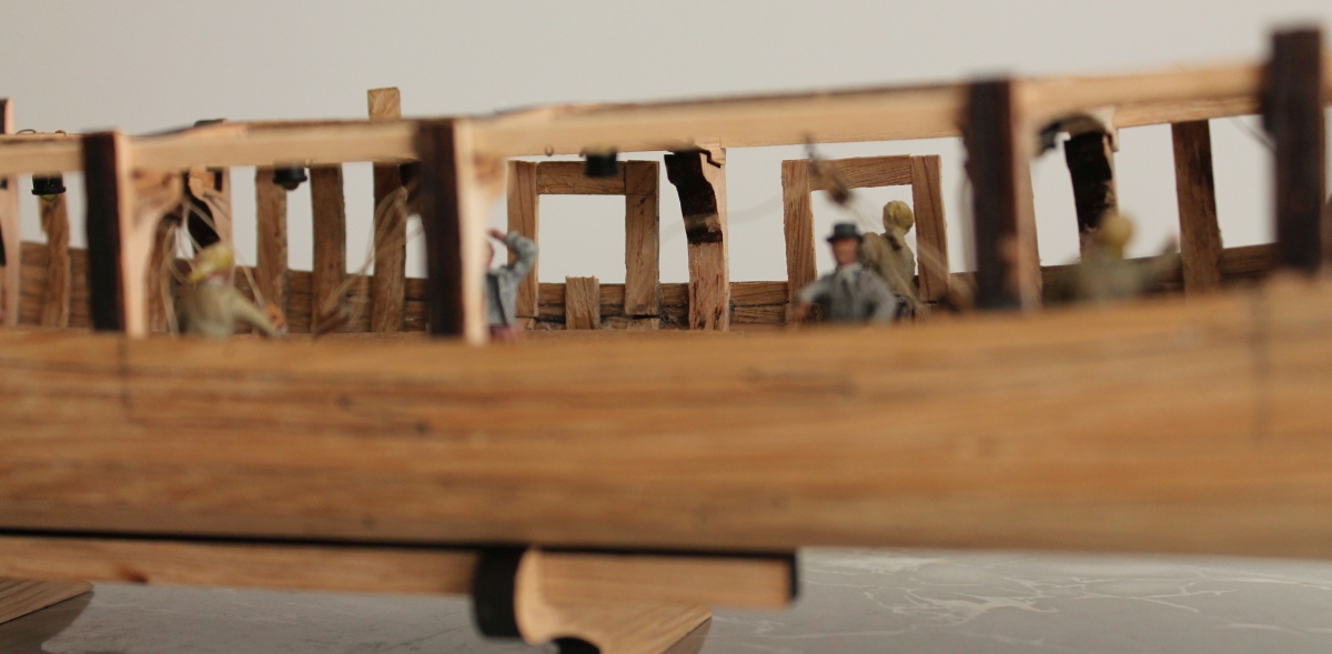
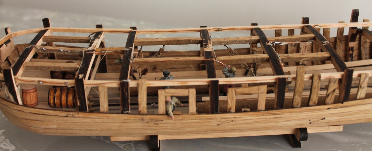
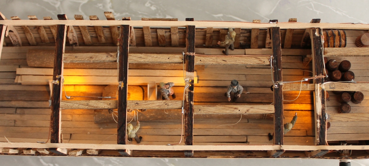
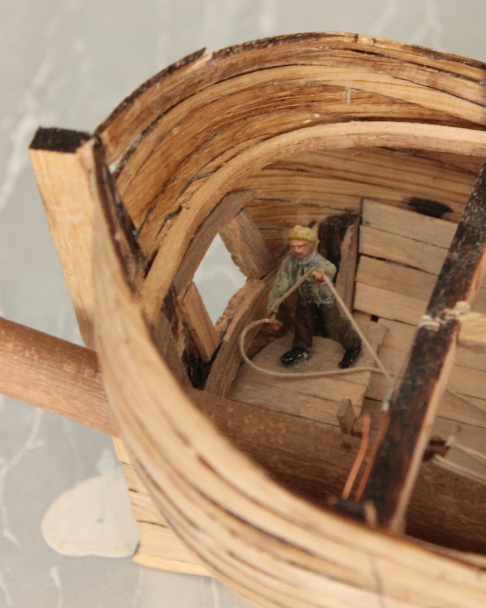
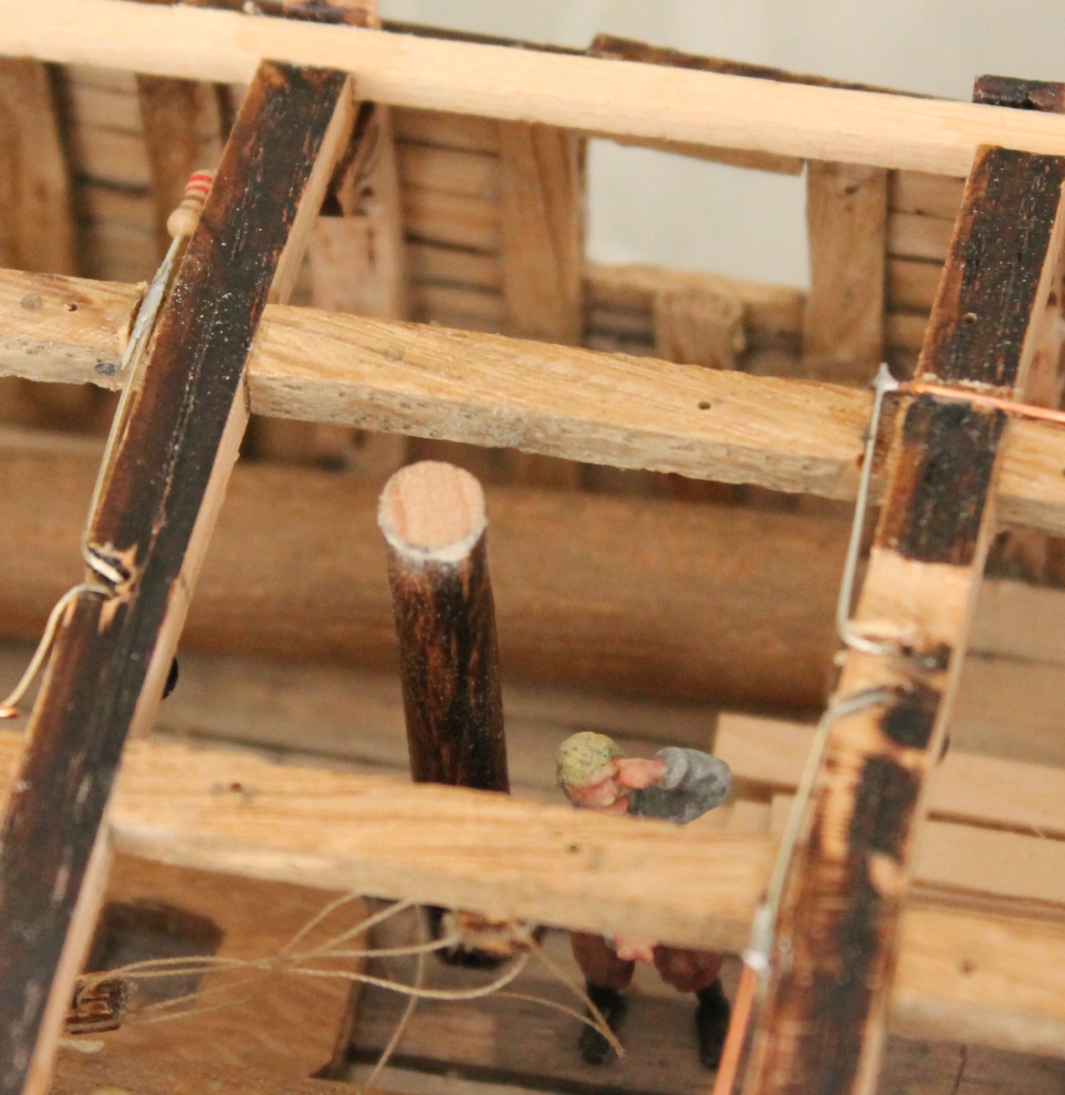
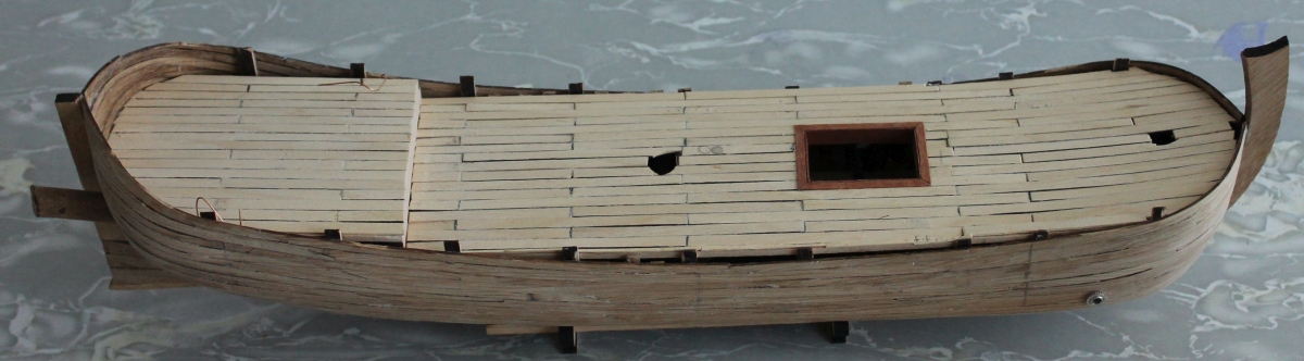
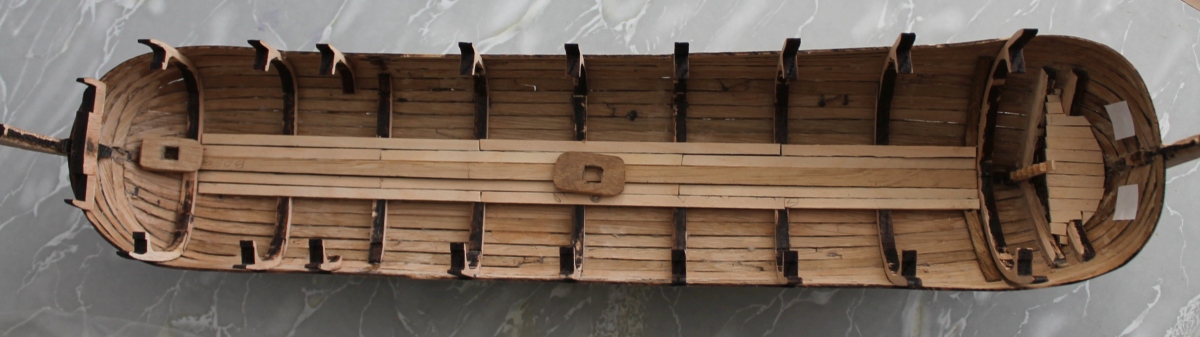
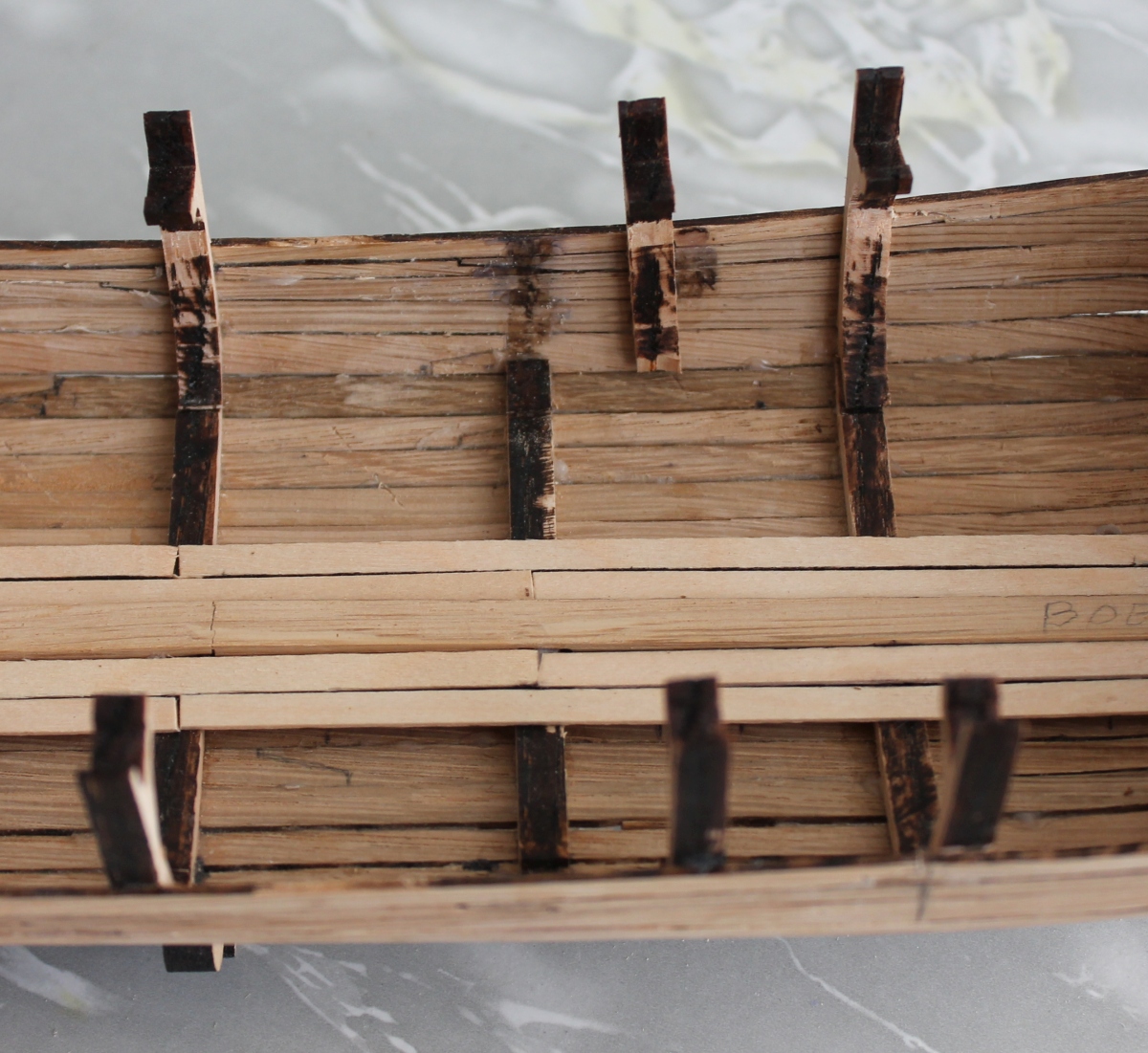
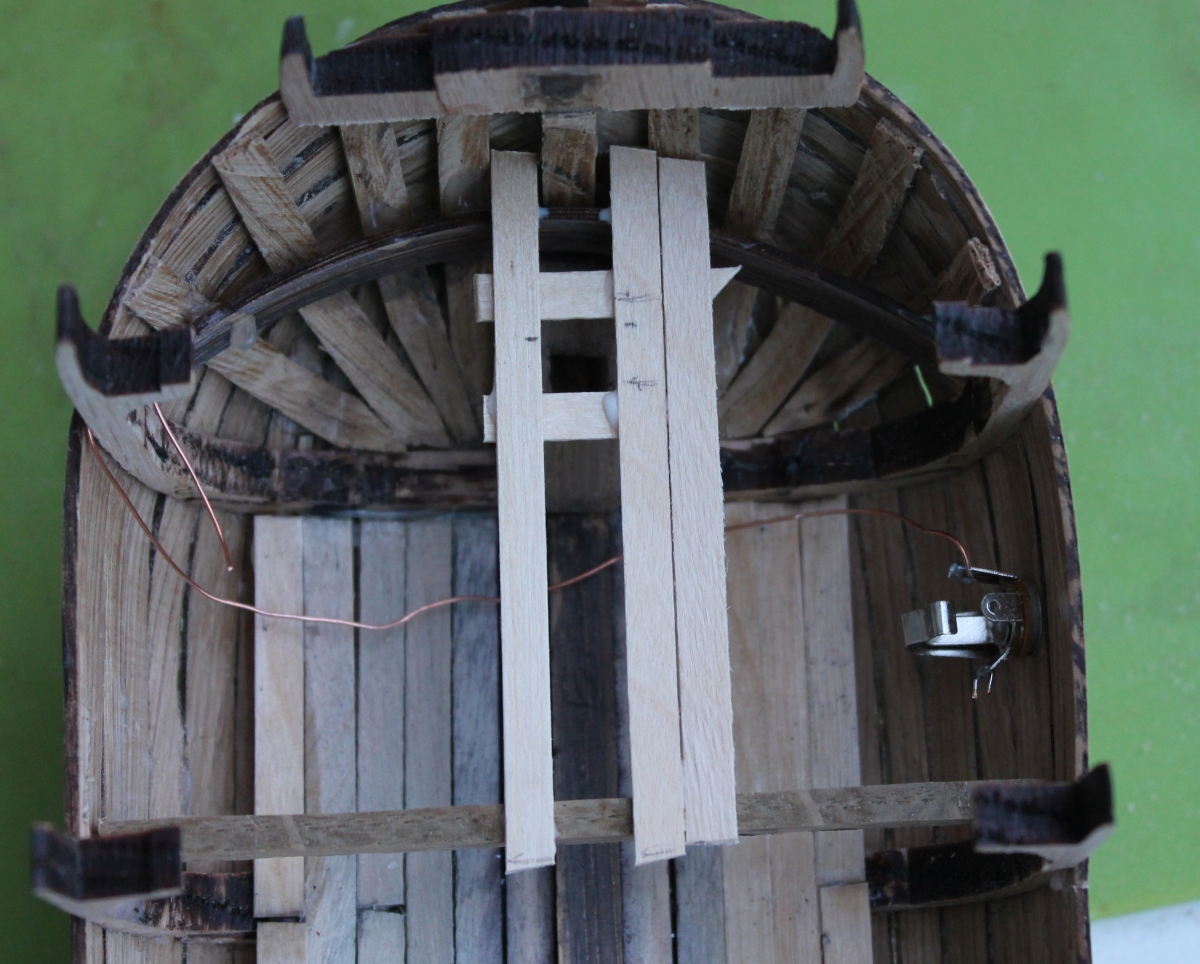
And on the inside it looks like this:
06-6-TotaalBinnen.jpg


On the rear two squares have been glued indicating the place where there should be two loading hatches. Furthermore, the spar is also in place and to the side of it two bottom planks.
Both mast tracks are still loose.
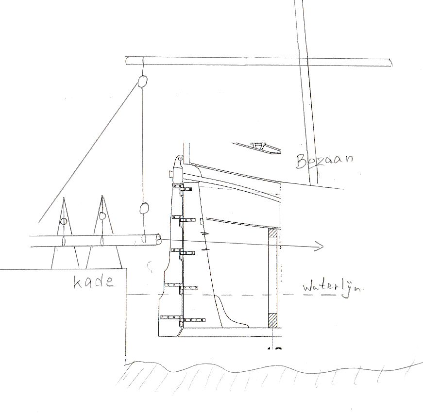
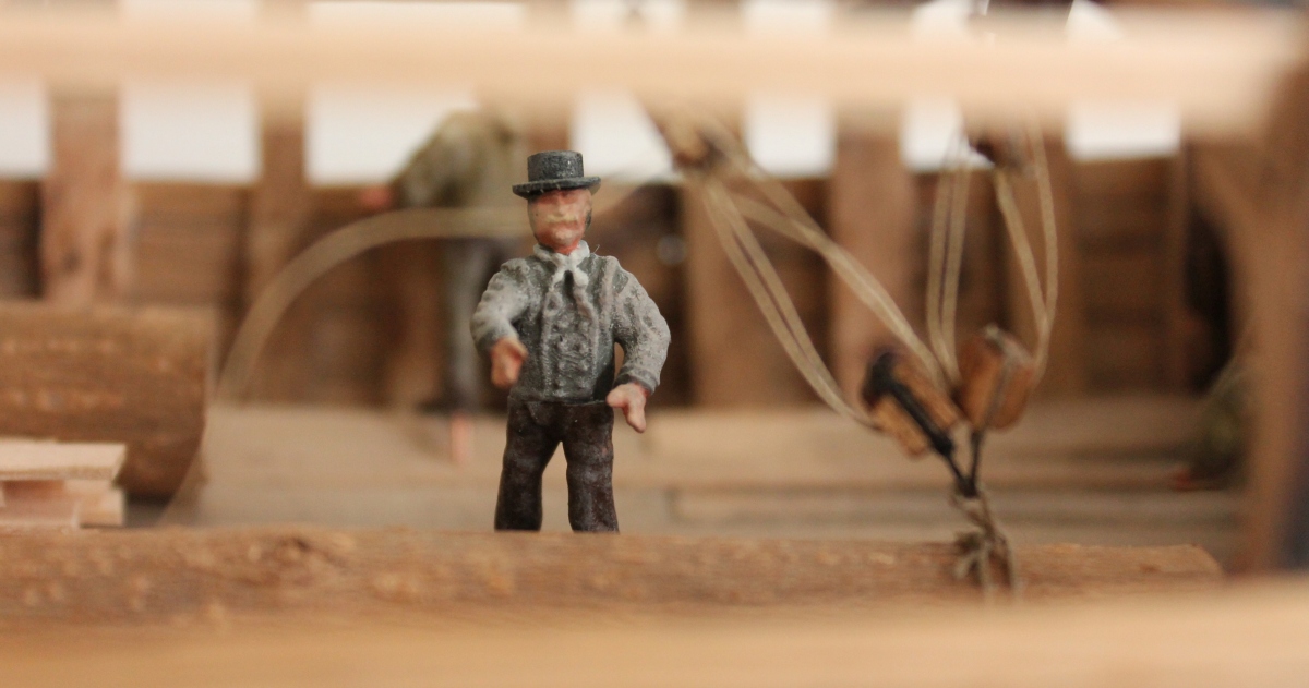
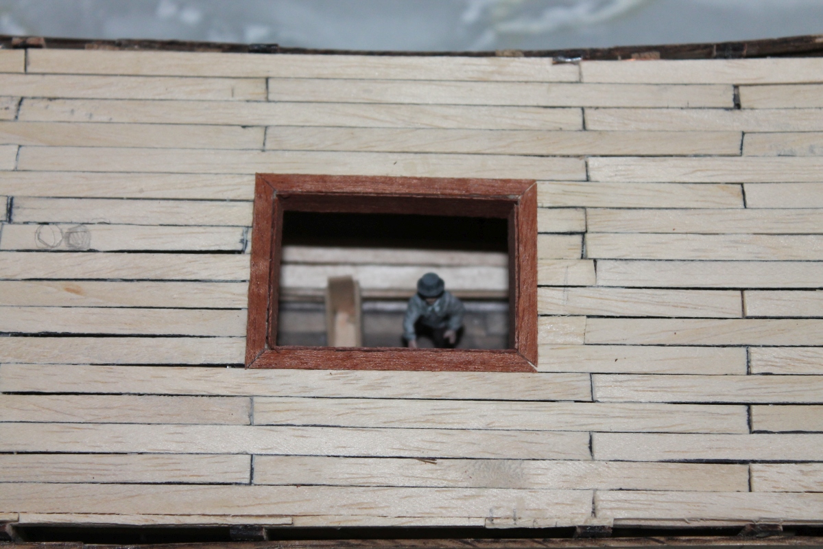
There will be four loading hatches. Two in the stern and two on the port side. If they are now loading logs hanging in the hoists, I think they will also have people inside to guide things. If you are then on the bottom and can hardly see anything to the outside, I don't think that's useful. So I imagine you want to stand right behind the hatch and be able to communicate with the people outside. Either a small platform under the loading hatches that you can stand on and look outside would be handy. So I made a small platform against the rear just below the cargo hatches with a climbing pole from the bottom.

06-7-BoegenBinnen.jpg


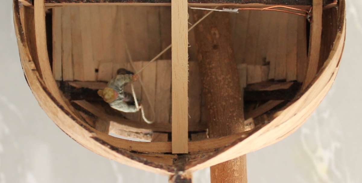
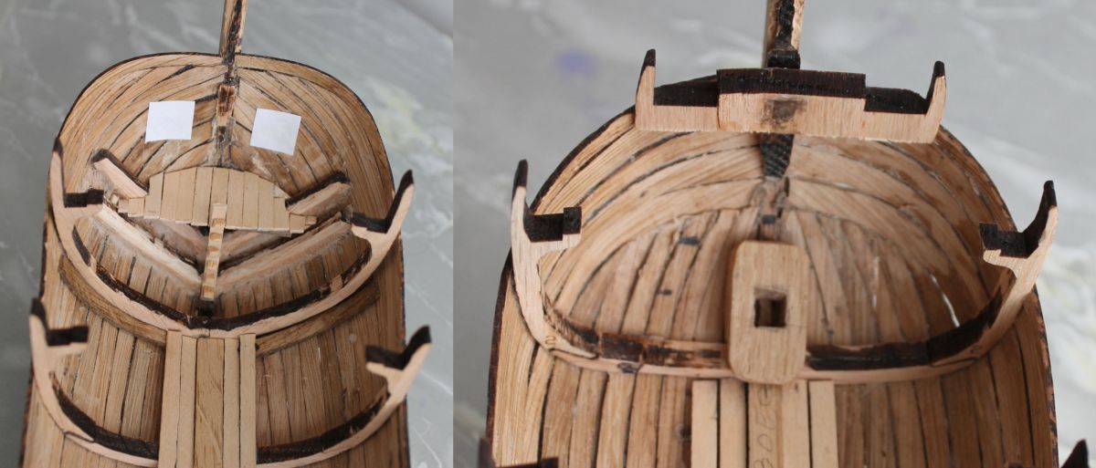
On the left, the stern with a little platform under the loading hatches. On the right, the bow with the mast track for the jib mast. That's where the turning trusses will be.
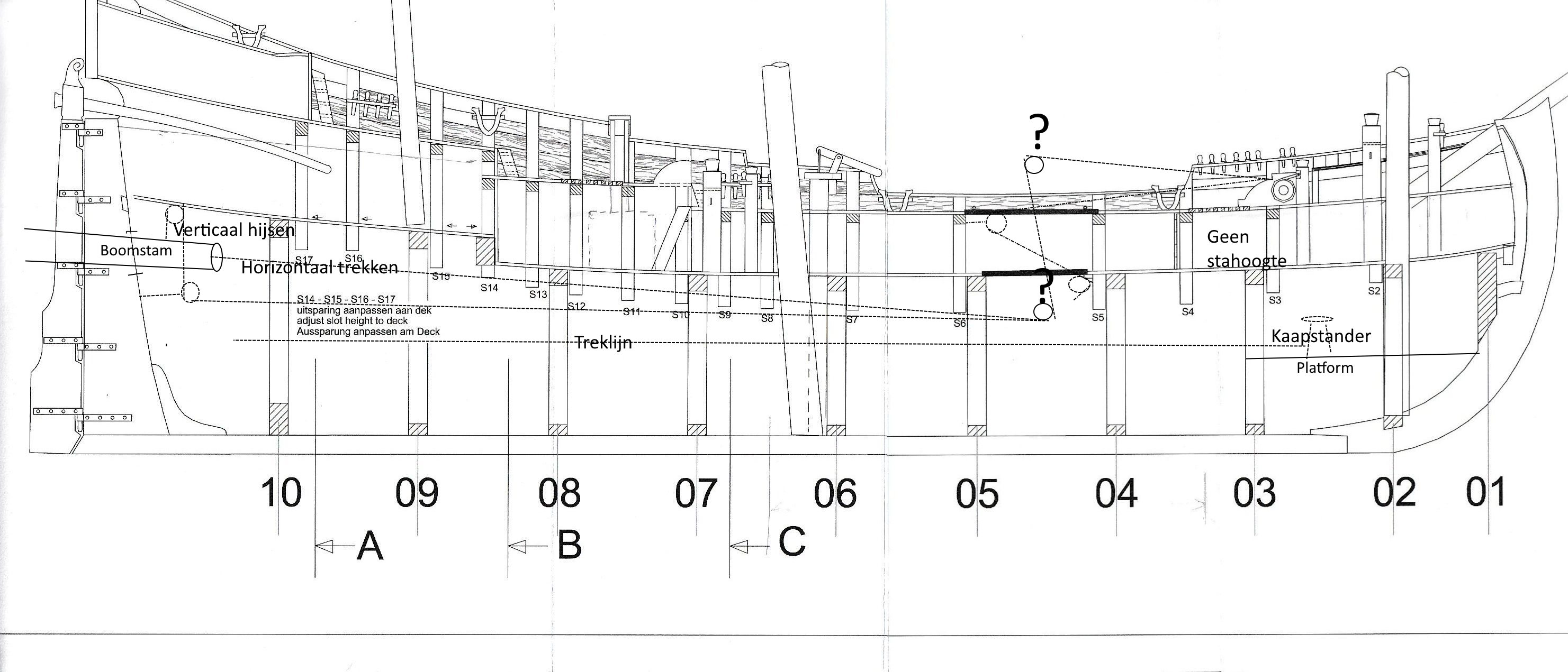
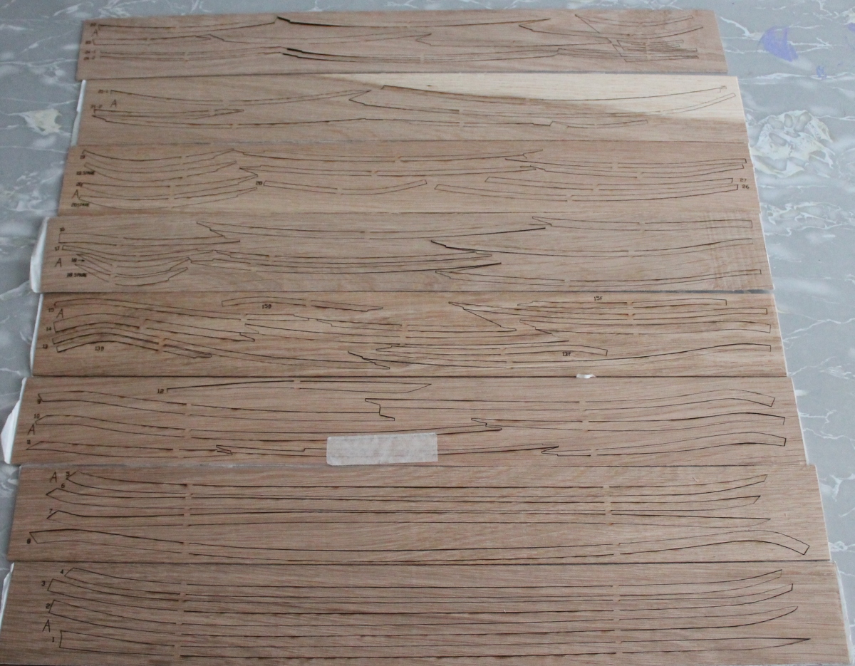
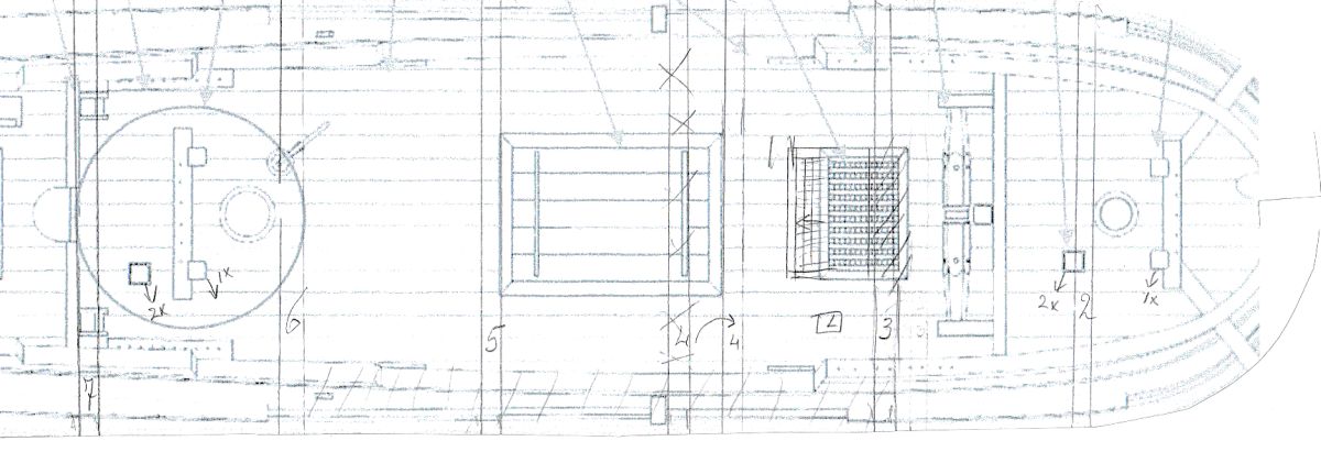
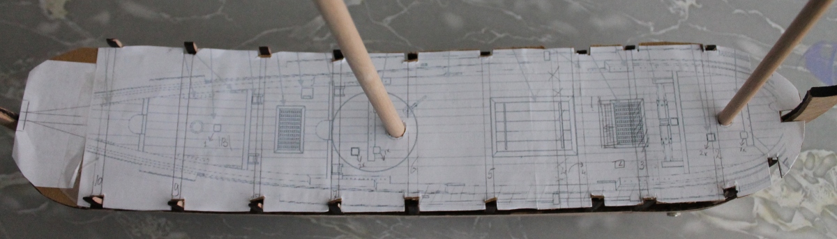
To get a good idea now of what to build on top later, I scanned the deck plan from the building description and printed it out in 1:1 scale with the model. Then I can put it on the model and see what needs to be built higher up.

06-8-Dekplan-BB.jpg


Then I see that one of the lower layer deck beams with corresponding truss no 04, runs exactly under the large deck hatch. I want to leave both hatches open so that beam has to go a bit to the side.

06-9-Spant4Verplaatst.jpg


This truss consists of three parts, the two upright parts of which I have detached and moved a bit. Through the head of the row of trusses I put a batten to determine the correct height of the relocated truss. Otherwise, I will have problems later when laying the deck.
On the heads of those trusses, deck beams will be laid for support of the deck. But I also need those deck beams to hang some lanterns (yellow LEDs) and a whole bunch of eyes for hoists.
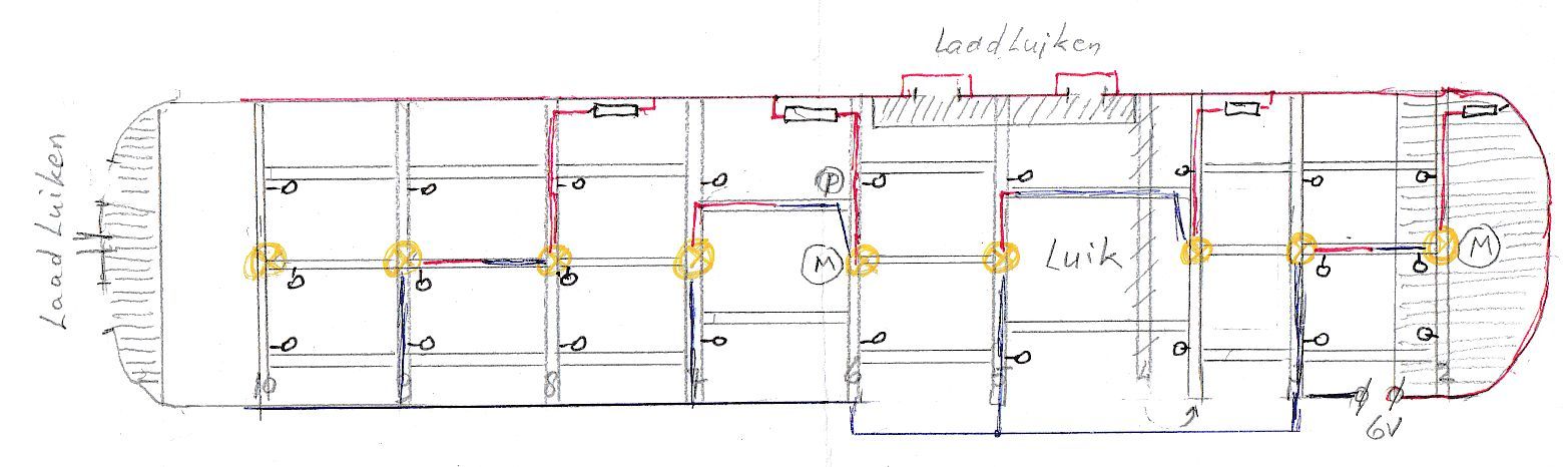
So I made a new deck plan.
06-10-Dekplan.jpg


Here you can see that deck beam 4 has been moved slightly forward so that the hatch is now clear. A little platform has also been drawn under the cargo hatches on the port side as well as in the bow. That will be a platform for some cargo. You can also see the locations of the yellow LEDs that will be supplied with 6 volts. The connector for this is at the bottom right.
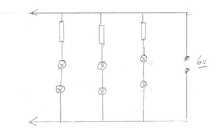
The principle diagram for the LEDs is the following:

06-11-Pricipeschema.jpg


Two LEDs in series with a resistor and that several times between the + and - of the power supply.
So there is a direct connection between the LEDs. On the deck plan, you can see that there is thus a direct wire running between the LEDs on different deck beams. That is why I am also making longitudinal beams between the deck beams where I can then hide the wiring behind. At the mast and hatch, I can only fit two elsewhere three.
There will also be double planking for the most part and I can also fit some wiring there.

To be continued.

Translated with www.DeepL.com/Translator (free version)
Modern technology in an old fashion ship. I Ike the idea, Jan. The oak is still challenging.
Regards, Peter
 
Update 7

Several items have been added.
First, the turning trusses in the bow. There will be a platform for this. I don't yet know whether I will also apply an interior lining here.
full


Here is also the mast track for the jib mast, and the connection for power for the LEDs can be seen at the bottom right. The first set is connected and still hanging a little above.

The stern has also been extended a bit, as that remains easily visible anyway.

full


There is a height jump between the last rafters and therefore the interior planking also runs with a height difference. The last section is completely planked.
The cargo openings are also framed inside. This gives a bit more sturdiness when cutting out the openings.
The floor itself has also been planked a bit further and given some colour. Not painted a nice shiny brown but treated with vinegar. Bear in mind that this is a overworked freighter which needs to do its thing as cheaply as possible.

full


Here the colour is easy to see. There are also some deck beams on here (still loose) with longitudinal beams. I need these to hang the lights from and to put eye bolts in which to hang the logs.

The deck plan I showed in the previous update was pasted on a piece of cardboard with notches at the level of the trusses so it can be laid flat over the deck beams. This gives me good insight into where certain things will be on the deck so I can take that into account underneath.

full


For example, the location of the mast tracks and hatches.
full


And this already looks a bit like the final result. The LED is too bright here. I'm thinking of sliding a cap around it, but that will come later. At least I know it works.

To be continued.

Translated with www.DeepL.com/Translator (free version)
 
Last edited:
Update 8

Have you ever thought about how you would load a log about 75 cm in diameter and about 10 metres long into a flute ship ?
And not now with some forklifts but some 400 years ago ?
Do the maths:
Cross-sectional area x length x specific gravity. π.r2 x l x
3.14 x 0.35 x 0.35 x 10 x 600 = 2308 kg. Over 2 tonnes. And all you are familiar with are hoists. And you know that you can multiply the force applied to the hoist by the number of lines between the blocks. You have some so-called four-loopers at your disposal. Such a hoist consists of two two-disc blocks so with four lines between them. So your strength is multiplied by 4. You are strong and can exert as much as 50kg of pulling force. So that is effectively 200kg. You want to lift that 2000kg tree trunk so you need at least 10 hoists with a male at each hoist who can exert at least 50kg pulling force. So real strong men, in other words.

OK. So you have a few men who can get it off the ground. But now bring the log into the ship and put it in place. With those hoists, you move it vertically but now horizontally?
The best way to show that is through a couple of drawings.

full


The trunk hangs from two (10) hoists A. The hoists B hang tension-free from eyes a little further into the hold. Now the hoists B are pulled while the hoists A are winched. Gravity will cause the trunk to hang more on the hoists B and thus move forward a bit. And repeat all this a few times.
You have seen from the calculation that two hoists is insufficient and at least 10 are needed. So it will definitely not have been an easy and harmless job.
The most difficult part will have been the first piece. Hoisting the log from the quay (I assume) in front of the opening in the stern and sending it into the ship, and then hanging it there and unloading it further and further on the quay. And unloading everything exactly the other way round. I'd like to see them do that now in the Rotterdam port. Probably not allowed by the labour inspectorate.

But there is also progress.
A decking has been started in the bow.

full


And after padding with some cargo, it looks like this.

full


The first LEDs are now also fixed under the beams, which are still loose but cannot be removed because of the wiring. That wiring can still be seen from above but not from the side opening. Further wiring will mainly be hidden behind the deck framing. The wiring will also be milled into beams and deck beams in various places. They should not protrude above the beams because then the deck will not lie flat.

Also, the hatches in the stern have now been opened.

full


This is a preview of the view later through the open section.

full


The inner frames of the cargo hatches on the port side are also in.
full


On the little platform in front of it, someone can take on the planks etc.

Part of the cargo can still be clearly seen below.
full


There are a number of planks/beams in front of the decking and two tree trunks in front of it. There will also be one hanging in the hoists, but I need to be a bit further along with the deck beams and lighting first.

And this is the overall picture.

full


To be continued.
 
Last edited:
Very interesting to see how you're progressing!

I'm from South Africa and did some research into the origin of my family - Marais. Charles Marais sailed on a dutch Fluytschip (Voorschoten) from Delftshaven, Holland on 31 December 1687 and arrived at Table Bay on 28 April 1688. Therefor this ship has some sentimental meaning to me. I was excited to see that there are sets being sold for building a fluytschip, however as I have no experience in model ship building, it looks like it would be an impossible task - at least for now. I'll start small and maybe one day be able to build this :)

Until then, I'll enjoy following your progress here.

Best of luck with the build!
 
Update 9

Returning briefly to loading logs or long poles for masts.
Hans' suggestion of using the spindle does present some problems.

full


A cable on the spindle then has to go through two hatches into the hold. Then I need two blocks that must have a suspension point above the hatches, where the two ? are. Tricky. May be attach to the front and back of the hatch. Then you can route the cable aft in the hold. An alternative to the spindle is a capstan e.g. on the platform in the bow. Where I now have some barrels. Then you can more easily bring a tow line aft. With such a line you can pull horizontally or hang it vertically via some blocks.
But what do you want to do with it ?You can attach the cable to the trunk then you can apply a horizontal force forward. But either way you have to hang the trunk on hoists from the deck above it, and move them forward alternately, as indicated in previous update. One advantage of the line via the capstan is that you need slightly fewer manually operated hoists. A capstan is easy to operate and you have great power.

But these are the operations IN the ship. Initially, the trunk is on the quay and has to pass through the loading hatches. How?

full


In the drawing above, the ship is manoeuvred and secured with its butt almost at right angles to the quay. On the quay, you can have one or more stanchions with which to hoist. With these, you can raise the trunk to the same height as the loading hatch in the ship. You can feed the line on the capstan through the loading hatch and attach it to the trunk. Then you can pull it horizontally towards the loading hatch.
With a hoist at the tip of the crossjack yard, you can bring the trunk in front of the loading hatch. With the capstan line, you can pull the trunk inside and then hang it on hoists as quickly as possible inside the ship. And then work further inside.

Unloading logs can be done in the same way. Only then you can't use the capstan line for horizontal force but you have to have something on the quay with which to apply a horizontal force.

Anyway, moving heavy objects horizontally with hoists is something that still happens today. Thank you Jinny.

full
 
Last edited:
In "Scheepshistorie" No 28, there is an article "Houthalen with ships from the Netherlands in a Norwegian bay".
There is some information from that.
But elsewhere I read that from Germany (via the Rhine) large rafts of wooden logs were transported to the Netherlands.
Also the documentation I have for the construction of the model of the Roman Rijnaak showed that its wood (oak) came from the Black Forest. So I suspect oak wood was brought in by rafts from Germany.
The forests in the North will have consisted mainly of coniferous wood. So the loggers will have mainly collected that kind of wood there.
The aforementioned article more or less indicates the same. The wood from there was often transported as planks. Short pieces were sawn, but the longer pieces were split from logs by hammering wedges into them that were kept wet. This caused the wedges to expand, splitting the log along the grain. This method was also already used by the Vikings.

So it seems less likely that heavy thick oak logs had to be transported from the North (not impossible), but more likely thinner and longer coniferous logs and planks thereof. I do not consider it impossible because Stephan has seen in John Harland's book that hoists on masts and yards were used to handle heavy loads.

The article mentioned describes some paintings and explains what can be seen on them.
Mainly, it shows people loading wooden planks through hatches in the sides of ships.
This method is probably much older than the 17th century as there are drawings of cogs with a loading hatch in the ship's side.

full


The nicest painting I like is this one:

full


Andries van Eertvelt (1590-1652) Oil on panel c 1625.

The ship on the left, here with a flat transom though, so no flute, is loaded through the aft hatches.


full


The text indicates that a hoist is attached to hoist the trunk in front of the hatch. (But how to proceed?) One log sticks in and some others are still in the water. The ship does lie askew possibly slightly on dry land. (For want of a nice quay) Below it, a raft is assembled from planks. And further to the right, a boat can be seen with short poles stacked lengthwise, probably for the ship on the right.

That painters sometimes knew more about painting than loading ships is shown in the painting below:

full

Aert van Antum (1580-1620) Oliver paint on panel. Ca 1615-1620

On the right is a raft of planks which are loaded as deck cargo. This would never have happened because the ship would have become far too unstable. To the left, a small boat with two short poles lies perpendicular to it. This too will not happen because of the resulting instability of the small boat.
To the left of that again, another small boat is dragging some poles behind it.
On the far left, you can see how some short poles are correctly stacked between two vertical poles.


In short, my sketch in my previous update, that a flute, lying against a quay, is loaded with long really heavy logs, does not seem very likely. That via those hatches long poles are loaded is certain. And that via the side hatches planks are loaded is also certain.

To be continued.
 
Last edited:
A Flute Ship in Oak.

For a long time I had planned to build a flute. A flute was the most common type of ship for freighters in the 17th century. They mainly sailed on the Baltic Sea with the "moedernegotie". Many were also equipped as wood grinders because shipbuilding was booming in the Zaan region at that time. A lot of sawmills were built there at that time which allowed logs to be cut into planks much faster.
The flute I wanted to build was to be a wood-carrier.

01-01-TekeningHouthaler.jpg

Photo: Wood-carriers

Since I didn't know a kit of it, it had to be scratch built. But given the shapes, that was going to be a challenge. And then Kolderstok came up with a kit. See:https://shipsofscale.com/sosforums/threads/17th-century-fluytschip-kolderstok.9394/
At the meeting in Duizel I told Hans van Nieuwkoop that I was planning to build a flute as wood-carrier. A little later I got an email from him asking if I was willing to build a Kolderstok flute in oak. Because Hans also wanted to optionally release the flute in oak. But first he had to build one on test. I was willing to do that for him. So Hans went to work hard to have all parts made in oak. And the result of that I have now received and can get to work.
Some pictures of the package.

01-02-InhoudDoos.jpg

Photo: Package contents.

01-03-Houtsoorten.jpg

Photo: Some of the different woods present.

01-04-Spantjes.jpg

Photo: trusses in thick oak

01-05-GeprinteFiguurtjes.jpg

Photo: Printed figures

01-06-EikenPlanken.jpg

Photo: Oak planks for the skin. In the normal package, these are basswood.

Hans had no problem with me making it a model to my liking. That's convenient because I'm a bit "allergic" to enclosed spaces. Or rather if something is built completely closed I want to know what is inside. And as I saw in the report of that other Hans, that flute has an internal hold without bulkheads, but there is nothing left of that. So that's not possible. So my flute will be opened up somewhat.
The flute has been developed as a wood-carrier version and I want to explicitly reflect that. That is, there will be some hatches in the side, as shown in photo 1, through which wood (planks/beams) will be loaded. And large logs will be loaded from the transom. So there will also be two additional hatches there. (I think) And further logs are in the hold. So the hold must remain visible. To that end, I think I will leave out a piece of ship's wall on the other side than the loading hatches. And to be able to see some inside, I'm thinking of some yellow LEDs as oil lamps. I am still considering if I will also make the cabin visible and thus provide it with some furniture and lighting. Then I will have to make a hatch somewhere in the stern. So I have plenty of ideas but let's get started first.

To be continued.
Translated with www.DeepL.com/Translator (free version)
Hallo Jan alias @janzwart
we wish you all the BEST and a HAPPY BIRTHDAY
Birthday-Cake
 
Update 11
After spending some time doing other things, it is now time for another update.
In one of my previous updates, you saw that I started adding lighting under the deck beams.
I have continued with that. However, this limits the accessibility of the hold so the stuff I want in there now has to be placed.

full


In the stern, a few more deck beams need to be placed. A few crew members can be vaguely seen here. More in detail below.

full


full


Here they can all be seen. But no wiring can be seen as the beams are in front of them.
full


From the other side, the wiring can be seen but that will soon all be closed.

full


And below, the LEDs can be seen, and working.

full


And from above: Here you can also see that between the rafters another three rafters have been placed. But also that the decking in front of the openings on the port side has been removed. The male here stands on the bottom and looks generously through the opening. So decking is not needed here.

full


Here he is on the bottom and can generously look through the hatch to see if anything is approaching.

full


And seen from behind.
full


To be continued.
 
Last edited:
Update 12
We have made considerable progress. Lighting has been fitted all over the deck. All the deck beams are in place. A trunk has also been suspended in the stern, which is still protruding through the loading hatch in the transom. The gangways up to the landing deck are in place.

View from the side.
full


Here the welds in the strakes can be seen quite well.

And the transom/ stern

full


Here, there are some things to note. The top strakes on the left are broken and not yet repaired. The right one is also broken but repaired. The thread of the wood runs strongly diagonal here. And exactly there, the batten has to be twisted quite strongly. This does not go together. There is a large gap underneath. The batten underneath runs slightly down towards the stem, whereas it should run horizontally there, as the batten above it does. A repair job. Furthermore, the cabin windows are lightly outlined. There will be open shutters for these as the cabin will be lit and fitted with furniture. This can then be vaguely seen. Furthermore, a piece of tree trunk protrudes from the right cargo hatch. According to the build description, the last gangway should come exactly to the height of the stem beam. So that sits nicely.

Here a crew member is pulling the hoist from which the stern trunk is hanging.
full


Tough job on your own. Later I'll add a second one but I couldn't hang that hoist because the eye is under the deck beam and thus barely accessible from above. Later when the sidewall is open I will be able to reach it.

No this is not the mast. You can just see the mast foot at the bottom left.

full


I almost forgot about this, but it's the pump. In the build description, it's only on the top deck, but of course it extends down below just next to the spar. And that will be visible later when the sidewall is open. So it should also continue on the intermediate deck.

The bow.
full


Looks good, little to criticise.

The cabin floor in progress.

full


Midway across the last three deck beams runs the first plank of the cabin floor. The cabin comes to midway between the two aft deck beams. The whole section between the deck beams will soon be open so you can just see into the cabin. The ceiling of the cabin will come out exactly at the top of the stem beam, which is then the bottom of the hen hole.

The mizzen mast will be on the centre deck beam, and then the space forward of the cabin and aft of the mizzen will be the space for the helmsmen. Soon to be clearly visible from the side.

Here you can see the beginning of the bulge in the stern.

full


If you look closely, you can see that the curve is stronger on the left than on the right. The bend is cut off slightly. This directly affects the length of the skin strakes. I had to shorten those on the right by 2 mm. There is some more to say about that upper skin passage.

full


At the top, you can see the shape of the batten in the flat plane. It is clearly wider in the middle at A than at the ends. Drawn slightly exaggerated here. If in the horizontal planes look at the top and bottom they have equal distances vertically. This is only possible if the lath runs like the middle picture. At the ends, the batten runs vertically and in the middle it runs diagonally. Seen straight from above, you see the lower situation. At A the lath is slanted and towards both ends it should twist to vertical.

Between A and right B, the thread of the wood runs diagonally through the batten, exactly where you need to twist it quite strongly. You can clearly see the result in the second image.

Finally, the cargo hatches on the port side.

full


The left one still gets a small batten at the top.

To be continued.
 
Last edited:
Update 13

Just a quick update.
The landing deck is in place With openings for the mast and jib mast and the main hatch for loading the hold. This deck remains visible through a small gap (2cm) on the starboard side.

full


Looking down through the hatch, the crew can be seen.

full


And so now to apply the next layer of trusses.

full


On this deck, some things are also added. I've decided that the forward section will be the crew's quarters. A couple of hammocks will hang there. Furthermore, the pump runs up through this deck and a glimpse of the galley can also be seen.
At the stern, on the raised deck is the cabin. It is intended to be somewhat furnished. In front of it is the helmsman's room and in front of that is the mizzen mast.
Lighting also needs to be installed in various places. And, of course, there will be a few crew members. Bert Mogelin, (a fellow builder on Modelbouwforum.nl) is already busy with his printer.
See: Mogelin.nl
To be continued
 
Last edited:
Back
Top