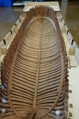
HMS Granado 1/48, POF, CAFmodel

Thank you !! The differences are striking.

You melt the paraffin in a bowl and then you spread it as the oil, correct ?

You need to be fast or you have enought time till it is solid again ?

Moreover, oil is known to have issues with glue (glue doesn'twork well). You mentioned that with paraffin glue works well. Am I understanding this correctly or it will be like with oil ?

Thank you !
Daniel
Hello Daniel

Apply low melting point paraffin wax (melting point 47°C, 115F) directly to the wood, do not melt into the ball.
As much as possible, do not paint the adhesive surface.
DSC03001.JPG
Even if paraffin is applied to the adhesive surface, water-based vinyl acetate-based adhesive can be used for practical adhesion without any problems. .

When heated with a hair dryer, it liquefies and penetrates the wood.
No solid paraffin remains on the surface of the wood.


Rather than linseed oil, you need to think about when to apply and when to apply heat.
Also, polishing is more important than oil-based, as the finish tends to change depending on the surface condition of the wood.

Thanks

Muchi
 
Thanks Ted

Aurora is not mine, but a work of a friend of mine, who is an amazing person who specializes in building structural models of sailing ships from scratch.
He also taught me paraffin wax.
 
Last edited:
Hi Muchi,

Does your glue still adhere to the surface by using paraffin on your frames?
Hi Maarten

Vegetable oil-based adhesives such as linseed oil have extremely low adhesion, except for cyanoacrylate-based adhesives, but applying paraffin wax has little effect on adhesion.
The paraffin I use is not melted and painted with a brush, but rather solid, so I often paint each part separately.

muchi
 
Hello Muchi. Be aware, that Paraffin, over time, will give a white thin film...it could even be peeled off or create white spots. Unless you know the good method.

Thanks Jim

When it turns white, heat it again with a hair dryer, it will liquefy at 50 degrees or more and permeate the wood again, so I think it's probably okay...
 
Thanks Ted

Aurora is not mine, but a work of a friend of mine, who is an amazing person who specializes in building structural models of sailing ships from scratch.
She also taught me paraffin wax.
She's a very good modeller then - pass that on - is she on SOS?

Ted
 
Hi Ted

I made a mistake, the aurora was created by a samurai-like man with his hair tied back.
I invite him to SOS.

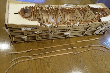
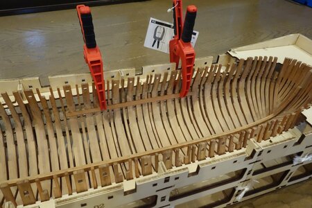
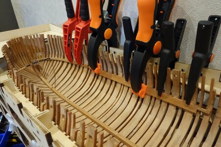
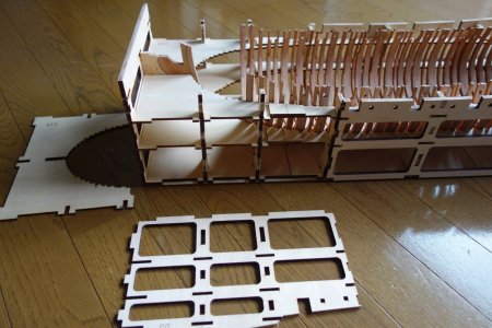
Now, since there are no cutouts in the hull jigs C13 and C14, I decided not to glue D1 to D3, C13, and C14.
There is no problem if you tie it with a packing string.
DSC03002.JPG


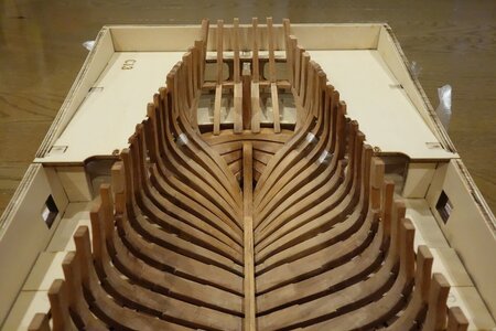
The jigs made by the bow frame group were excellent.
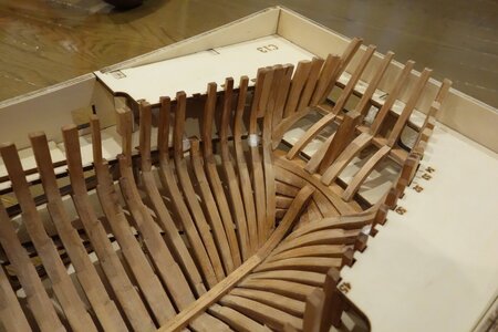
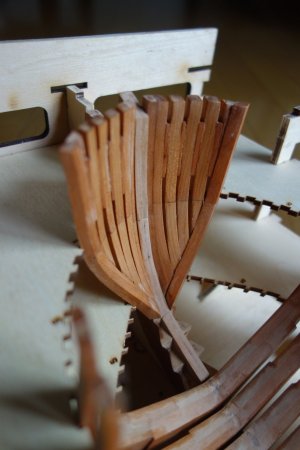
It was easier to glue the bow frame and rib1# together before attaching to the keel.
DSC03004.JPG

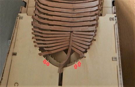
The bow frame group will not enter unless the protrusion of the red arrow of C14 is cut off.
DSC_0513a.jpg

I checked the rib height again and glued the keel and ribs from the front.
DSC03010.JPG

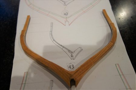
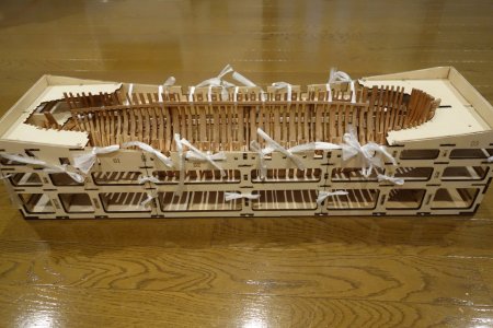
Temporarily fixed the top of the frame before sanding.
It is convenient that the strap for packing can be used for adhesive fixation.
DSC03015.JPG

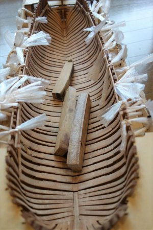
I was sweaty and did the sanding by hand.
(Work in the garden when there is a lot of wood waste.)
DSC03030.JPG

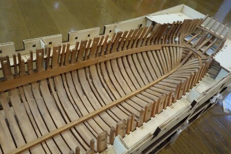
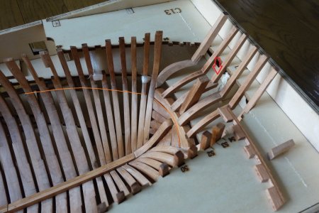
I glued the keelson.
When the rear frame is made, No. 1 is finished.
The red arrows cut out the jig.
2A-13 and 3F-5 can be attached.
I would like to attach 3A-3 that comes with No. 3 for positioning and strength.
The orange line is the dividing line.
DSC03046a.jpg

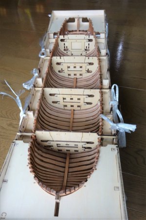
I used a template to check the position of the Deck clamp etc.
This is a template that is very helpful because it is easy to make errors here, but you need to be careful because the position of B in No. 1 is likely to be mistaken about 2 mm below.
DSC03040.JPG

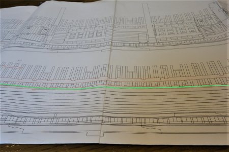
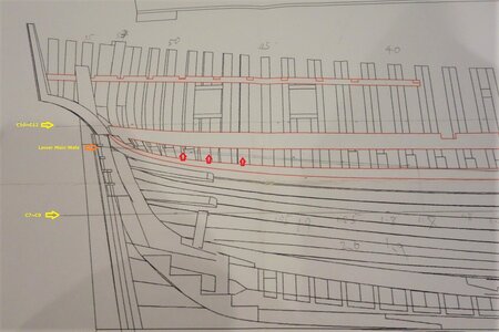
The cutting line when dividing the bottom of the lower main wale into upper and lower parts with a thin saw is on the deck clamp of the green line.
If I cut, I plan to cut just above the Deck clamp.
After cutting, I plan to stick the wale on the upper part of the hull to a little below the cut line.
It seems that cutting will be difficult if Mortar pit beam is attached before cutting.
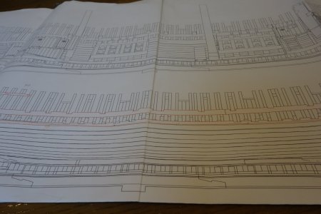
DSC03043.JPG

DSC03043a.jpg

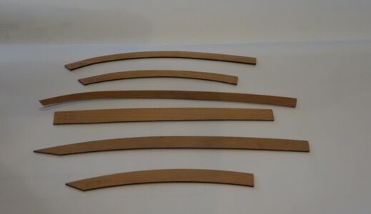
I plan to use the thick plates in the ship if I can process the materials from the kit and use them.

The cut of the outer plate of the CAF model is a problem, but with my technical skills, the width of the outer plate of the kit varies a lot and the curve is a little unnatural, so I don't think it will fit well. I plan to purchase the outer plate separately.
My favorite hull panels have few grains and stains, and the width of the hull panels other than the bow should be even on the top and bottom, and only the bow should be slightly curved.
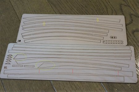
DSC03045a.jpg
The assembly instructions for No. 3 do not include an explanation of the upper/lower division nor a diagram of the division.
The upper and lower division of the hull seems difficult to me, and I feel that it is 30%.
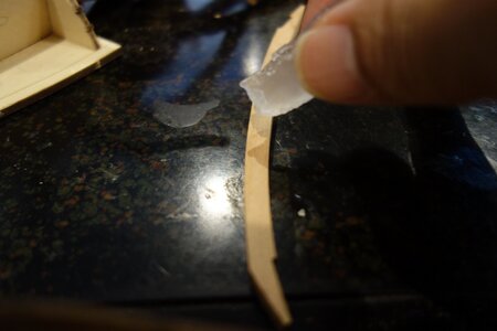
 
Last edited:
Thank you all for your 'likes' and comment.
Installed the stern frame.
The 5i-55 was not laser cut on the 5i plate in the parts list. Since it is a simple part, I made it with leftover wood from the kit.

DSC03051.JPG

I glued 2A-13 to 4j-h1 first.
3F-5 is the part through which the rudder passes, so I didn't install it yet.
The tie beam included in the No.3 kit was attached first to determine the position and improve strength.

DSC03050.JPG

Fine-tuning for the fit of Stern's frame is also difficult.
 
Your stern construction is looking very good - keep on this high performance
 
Thank you Uwe.
Thank you all for your 'likes'

DSC03074.JPG

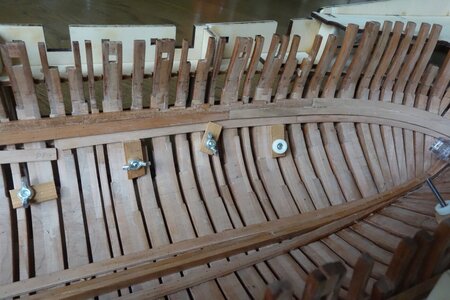
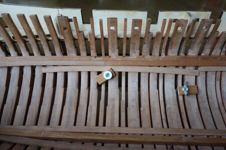
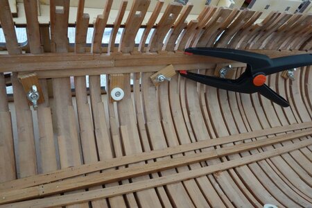
It is very difficult to bend the beam clamps to match the curve of the hull fore and aft, to align them precisely, and to adhesively fix them so that they do not shift.

DSC03066.JPG
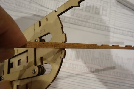
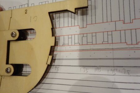
The B of the beam clamp is 5mm wide and the template is 7mm wide.

DSC03064.JPG
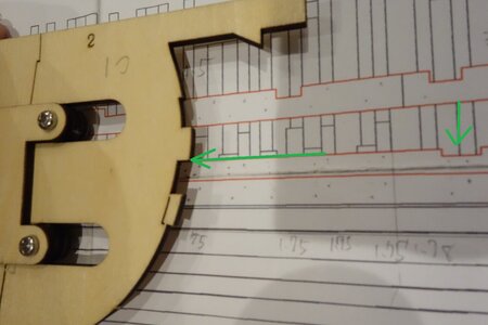
When comparing the template and the drawing, I think that the upper part of the dent should be the reference, but the arrow in B in the instruction manual seems to be the lower part of the dent.
I think it's fine as per the drawing, but I've stopped worrying about it for a week.
 
The clamp for the mortar beams should be at the upper edge of the template

DSC03064.JPG

I think, that the prepared notch for the clamp in the template is slightly bigger (7mm) so it easier also later on with the assembling and disassembling of the template - you will need them also f.e. the correct height of the smaller decks etc.....

I am following the drawing and until now everything is fitting well
 
Just one other important remark.

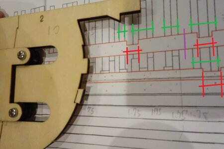
Be very accurate in the correct location (fore and aft) of the clamps - better the correct location of the notches for the beams.
Their location (red) can be exactly defined comparing with the frames (green)
also the two joints of each clamp (purple should be made very accurate

everything later on of the interior with decks and walls, small beams are prepared in such a way, that they fit between the to mortar bed construction towards stern and towards bow

DSC03064 (1).JPG

Our friend @Adiefenbach had here some problems with an slightly incorrect allignment

 
Uwe thanks for the accurate advice. Uwe
Start from the thickstuff strake C2 in the center of the hull, which is easy to set and position.
DSC03076.JPG
Glue B2 using C2 as a reference (B2 has no thickness at the top and bottom and has grooves for supporting beams, so using C2 as a reference makes it possible to bond more straightly.)
DSC03077.JPG

Using the top of the first and second layers of the layer as a reference line helps locate and mark the part (56 mm and 96 mm from the bottom of the keel).
The deck clamp at the rear of the hull has moved 3~4mm to the main wale line as indicated by the red arrow.
When cutting the hull with a fine saw, cut along this deck clamp.
DSC03081a.jpg
Even with water and heat, I couldn't bend the thickstuff to the thick direction of the board at the rear of the hull.
In addition, the frame at the rear of the hull cannot hold a 3mm thick plate with a single layer, and the upper and lower frames may come off. It may be better to attach the inner hull first.
DSC03084.JPG

The bow, stern, and thickstuff are not completely crimped due to the obstruction of the jig, so there may be gaps and insufficient bond strength.
I think my hull is hard to split as it lacks strength which is most important when splitting the hull up and down.
DSC03083.JPG
 
Last edited:
with all the problems of bending and installation of these thicker material - your result is looking very good Thumbsup
 
Mochi, I think you will find the hull will stiffen up considerably as you add the internal planking and timbers - It certainly won't be weak.

Ted
 
Thanks Guys.

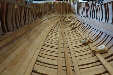
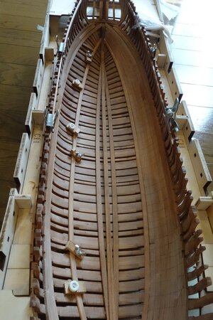
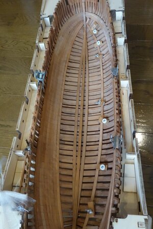
I decided to stick a thick plate from the top of the hull. ・
DSC03092.JPG
The curves don't match. ,
Even if you put 4 pieces together, the length to the stern is not enough.
DSC03091.JPG
I glued it by force.
It takes time to paste from the top because the thick plate does not fit.
DSC03094.JPG
The bottom plate is about twice as thick as the top plate.
The maximum width of the thick plate is 1 cm, and it was cut to about 6 mm.
DSC03108.JPG

I use 2.5mm x 6mm cherry stripes for the thick stuff that runs along the joints of the lower and middle
DSC03104.JPG
It looks like it will take some time here.
DSC03107.JPG

DSC03106.JPG
 
Last edited:
So you did not use the original thinner planks of the kit, but used another thicker one to immitate the "thick stuff" planks?
 
Back
Top