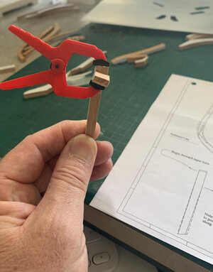
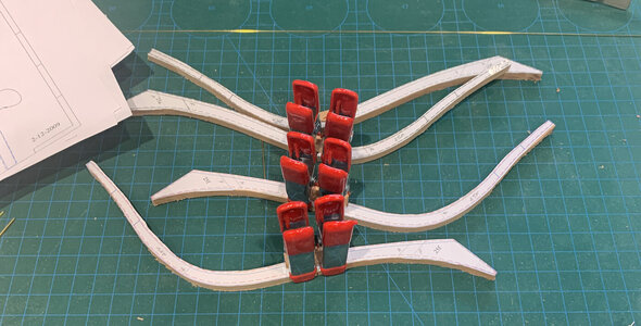
Excellent work Peter, at the moment I am busy with Le Rochefort and I am doing similar to you. I also glue my paper very close together to only have to make one cut, it saves time, wood and saw blades.
You are using an out of date browser. It may not display this or other websites correctly.
You should upgrade or use an alternative browser.
You should upgrade or use an alternative browser.
HMS EURYALUS - 36 GUN 1:48 SCALE
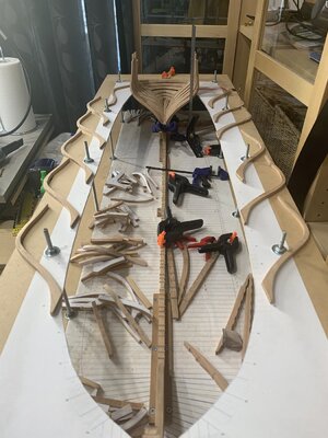
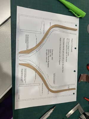
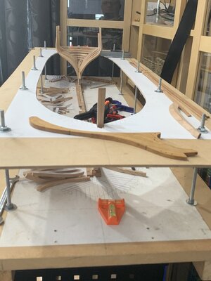
I really like the reference board, but that is a LOT of parts to cut out !I finally managed to get all the templates for the aft section of EURALUS peeled and stuck to the appropriate thickness cherry planks. I have also managed to get the reference board cut, drilled and mounted to the building board. Some weeks to do at each end is all that remains but I can get onto frame assembly and dry fitting to the keel now.
View attachment 355429
View attachment 355430
- Joined
- Dec 30, 2021
- Messages
- 278
- Points
- 278

Yep,I really like the reference board, but that is a LOT of parts to cut out !
The reference board means I have the side to side alignment and a raised centreline ready for frames. The templates have the reference line on them so when I assemble each frame I can check it against the plan, then fit a thin plank across its face at the reference line with the centre marked. Then I drop the frame into the building board and the plank should rest on the reference board with the chock/floor in the rising wood and I can sight the centreline to make sure everything is square and symmetrical. This is where the original build had gone wrong and I feel if Russell had used a reference board, his build would have been perfect.
There are over 900 components that need to be cut out by scroll saw for the framing alone which is why I tried to retain as many of the original frame components as I could.. There are up of between 6 and 11 components per frame (including the chocks) and there are 114 frames (including can't frames but excluding fashion pieces) to make. It's not difficult work; it's just time consuming. The frames around the midships are the easiest to make as there is little bevel to deal with.
I made up F30F (one of the aft can't frames) to see what it's like to make the beveled chock scarf joints. Tricky connection and patience is needed as one creeps up on the right lines with a chisel, razor saw and diamond file.
Last edited:
- Joined
- Dec 30, 2021
- Messages
- 278
- Points
- 278

- Joined
- Dec 30, 2021
- Messages
- 278
- Points
- 278

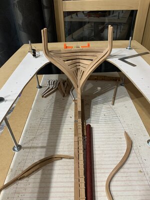
Ok so framing is moving along at about 1 frame station a day. I think this will pick up as I'm working on the aft can't frames at present with F31A glued in a F31F ready to bevel the deadwood join. The chocks are a little more complicated then I originally thought as the bevel on the forward face differs to that on the aft face so a lot of careful fitting up with files is need to get the right fit.


- Joined
- Oct 17, 2020
- Messages
- 1,336
- Points
- 393

frame already finished? Thank youOk so framing is moving along at about 1 frame station a day. I think this will pick up as I'm working on the aft can't frames at present with F31A glued in a F31F ready to bevel the deadwood join. The chocks are a little more complicated then I originally thought as the bevel on the forward face differs to that on the aft face so a lot of careful fitting up with files is need to get the right fit.
View attachment 355965
View attachment 355966
- Joined
- Dec 30, 2021
- Messages
- 278
- Points
- 278

Each cant frame station eg F31A has a port and starboard. It’s not until F24A that I start full framesframe already finished? Thank you
F31A means Frame31Aft. Each numbered station has a forward and Aft frame connected at the chock/floor however this doesn’t strictly apply to the cant frames.
Not sure the explanation helps
- Joined
- Oct 17, 2020
- Messages
- 1,336
- Points
- 393

Hi Peter, sorry I can not understand (translation) Thank you for answering me.FrankEach cant frame station eg F31A has a port and starboard. It’s not until F24A that I start full frames
F31A means Frame31Aft. Each numbered station has a forward and Aft frame connected at the chock/floor however this doesn’t strictly apply to the cant frames.
Not sure the explanation helps
- Joined
- Dec 30, 2021
- Messages
- 278
- Points
- 278

I was guessing at what you meant by your question. Perhaps the translation didn’t help. Please feel free to use your parent language and I will try another translator programHi Peter, sorry I can not understand (translation) Thank you for answering me.Frank
I feel your pain with double sided tape. Have you looked at Elmer's rubber cement? I used it for all my templates on frames. Comes with a brush inside the lid and you simply paint it on the timber then press the template down. Stays on as long as you want and then peels off easily.Wow, 2 days and I managed to print and cut out all the aft frame templates and get about 1/5 onto timber ready to saw.
I guess this is the tedious part of fully framed model ships... that and trying to peal off the backing on the self adhesive label material.....
Next job is to sort the templates into the appropriate material thickness piles before working out the best way to fit on the Cherry material.
Jigsaw arrived this afternoon so I will charge it and then cut out the reference board.
View attachment 355029
I bought it from Craft Online in SE Qld, but they are currently out of stock.
You can see it in use on this page of my build log. HMS Medea
- Joined
- Dec 30, 2021
- Messages
- 278
- Points
- 278

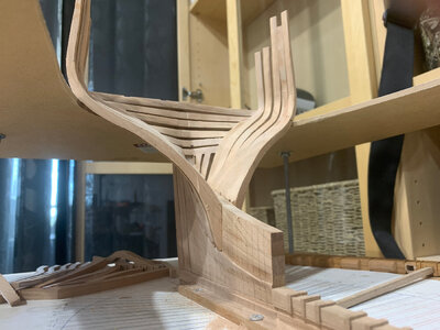
Thanks to another modellers suggestion, frame construction has speeded up to three frames per day. I had a 3/4" chisel in the locker in the apartment garage. I brought it up and sharpened it and it works ok. I need to work on the blade though as it's not a clean edge (from past misuse?). The larger chisel makes chock making simpler and faster than sawing and filing and provides a nice straight angles surface so you can be assured of good connection between parts.
I have finished installing Fashion Piece, 31A, 31F, 30A, and 30F with frames 29A, 29F and 28A assembled and waiting for treenails then installation. Frames 28F, 27A and 27F are cut out and waiting for chocks and glue-up. I also have frame components for frame stations 26, 25, 24, 23, 22, 21 and 20 cut and ready to go.
Had one disaster with 29F port side. The 3rd futtock foot snapped when I was preparing it for the chock. This was the second frame where I was to use an original component from Russel's build but alas I realised it was just too close to the line for me to use and have some wiggle room for fairing. If I had to make one replacement component on that frame, I might as well make both futtocks.
Oh yes, the bow piece has been tapered and given a coat of shellack (foreground). The rude too has been completed (timber wise anyway) and give a coat of shellack and a Tasmanian Oak tiller shaped and dry fitted (background).

- Joined
- Dec 30, 2021
- Messages
- 278
- Points
- 278

Ah, Disaster.
Realised I was aligning the foot of the frames at the deadwood to the wrong frame line (1/2 frame out). It appears I failed to taper both sides the foot of frames at Station 31A&F and 30A&F on the starboard side. I managed to remove 30A and 30F with little damage the foot of the frames or the deadwood thanks to a very sharp thin blade and the fact the glue had not full cured.
I am in the process of cleaning up the feet to the right taper on both sides and then check the alignment at the deadwood as well as the reference line.
Lesson:
Need to work out a sequence to make sure all the parts are cut, assembled with chocks, tree nailed, pre-faired then tapered before removing the template and cleaning up the frame for installation. I recall that Talley Ho had one of those check off boards on the wall of the workshop to make sure all the frames went through all the stages of preparation prior to installation.
Well I am back to where I left off before discovering the issue with the starboard can't frames. I have done some further fairing by hand held sandpaper to see that the alignment is true on the inside. If it's right on the inside, the small extra on the outside should fair in nicely. I picked up the issue when I noticed that Frames 30A and 30F albeit correctly aligned on the reference board, were not vertical as they rose above the reference board. The way I have the building board position, I get a perfect view of the port frames but only a side on view of the starboard frames so I will need to move the trolley out into more open space when fitting the frames to get a better view from all angles.

Great thing you found it when you did rather than after it cured !Ah, Disaster.
Realised I was aligning the foot of the frames at the deadwood to the wrong frame line (1/2 frame out). It appears I failed to taper both sides the foot of frames at Station 31A&F and 30A&F on the starboard side. I managed to remove 30A and 30F with little damage the foot of the frames or the deadwood thanks to a very sharp thin blade and the fact the glue had not full cured.
I am in the process of cleaning up the feet to the right taper on both sides and then check the alignment at the deadwood as well as the reference line.
Lesson:
Need to work out a sequence to make sure all the parts are cut, assembled with chocks, tree nailed, pre-faired then tapered before removing the template and cleaning up the frame for installation. I recall that Talley Ho had one of those check off boards on the wall of the workshop to make sure all the frames went through all the stages of preparation prior to installation.
Well I am back to where I left off before discovering the issue with the starboard can't frames. I have done some further fairing by hand held sandpaper to see that the alignment is true on the inside. If it's right on the inside, the small extra on the outside should fair in nicely. I picked up the issue when I noticed that Frames 30A and 30F albeit correctly aligned on the reference board, were not vertical as they rose above the reference board. The way I have the building board position, I get a perfect view of the port frames but only a side on view of the starboard frames so I will need to move the trolley out into more open space when fitting the frames to get a better view from all angles.
View attachment 356818
- Joined
- Dec 30, 2021
- Messages
- 278
- Points
- 278

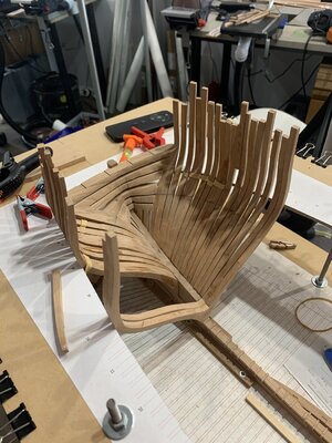
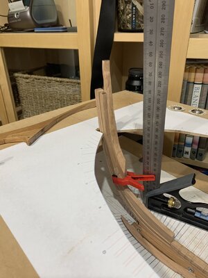
Still have bunch of cant frames to install (now they are all made) but I wanted to test fit my first full frames (24A and 24F) to see their fit on the rising wood. Nicely surprised to see them slot in with a little push.
Have completed installing Port side aft cant frames. Just need to install the starboard 27A & F, 26A & F and 25 today then 24A & F full frames and I will stop to do some internal and external fairing to make sure I am still on the right path.
The first of the Bollard Pieces and been made and dry fitted to the stem.


Last edited:
Hello Peter, what a beautiful sight of Euryalus growing, very neat work.
- Joined
- Dec 30, 2021
- Messages
- 278
- Points
- 278

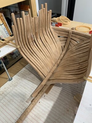
So all the aft cant frames are in as well as the first full frames 24a and 24f. I have also dry fitted 23a as well as Keelson 6 and the sternum knee to see how things are progressing. Some minor fitting to be done between 23a, 24f and the keelson to neatly fit the taper.
I have also done a preliminary fairing of the frames from transom to 24f and all looks well so far.
I am now turning my attention to the bow with the bollard and hawse pieces to be scrolled out today as well as frames Va and Vf.
I have also done a preliminary fairing of the frames from transom to 24f and all looks well so far.
I am now turning my attention to the bow with the bollard and hawse pieces to be scrolled out today as well as frames Va and Vf.

- Joined
- Dec 30, 2021
- Messages
- 278
- Points
- 278

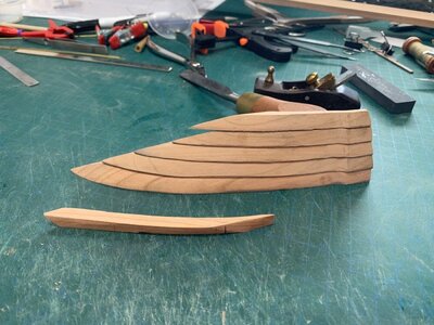
After a couple of days scratching my head over why my templated Bollard/Hawse pieces did not fit nor match the pictures in Allans book, I finally realised that I had misinterpreted the drawings. I had mad the assumption that the blue outlined parts were flat (like the frames) but in fact I should have realised that the blue outlined parts were the forward face of the parts.
Having thrown away the first set, I have a starboard side set made (and a couple oof spares as I tested the various alternative configurations/interpretations of the drawings).
After scroll sawing the shape, I also chose to carve the taper in these parts out with a sharp 12mm chisel instead of using the drum sander.

- Joined
- Dec 30, 2021
- Messages
- 278
- Points
- 278

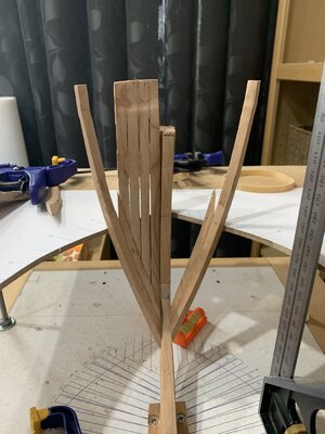
Getting on with fitting the Bollard/HawsePieces as well as Frames Zf and Za. Had all sorts of difficulties envisioning the way the Bollard/Hawse timbers fitted the stem and Frame Zf so I decided to make and fit Frames Zf and Za first so I could see the gap in which the Bollard/Hawse timber pieces went. This was simplified further by assembling Bollard and Hawse timbers 1, 2 and 3 leaving Hawse Piece 4 to fit later with the filling piece.
While things were drying, I got on with finishing the assembly of Frames 23a, 23f, 22a and 22f and started assembly of Frames 21a and 21f.
I also need to finish scrolling out Frames 0 thru 10, the start cutting templates for the front end of the ship.
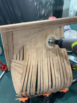
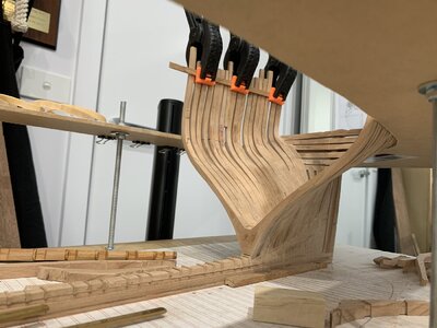
I also finished the preliminary fairing internally and externally off the aft end of the ship. I employed Dremel's 60grit 30mm diameter sanding disk for this mounted in my Ryobi R18RT rotary tool. It has more power and lasts longer than my Dremel 8220 and a slightly smaller handpiece.


