HM Sloop Fly, 1776 - scale 1/36 by own reconstruction and the books from David Antscherl

Joined
Oct 23, 2018
Messages
526
Points
353

HM Sloop Fly was one of 26 Swan Class ship sloops built to a design by John Williams. The keel was laid in January 1776 at the George White Shipyard in Sheerness. The launching took place on 14.9.1776 and the commissioning on 19.10.1776.
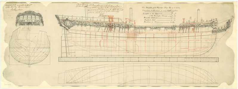
FLY_AsBuilt.png
Source: https://commons.wikimedia.org

Between July and September 1778, the sloop was refitted in Porthmouth and the underwater hull was coppered.

The armament originally consisted of fourteen 6 Pdr guns on the upper deck. By Admiralty Order of 22.7.1780 the armament was increased by two further 6 Pdr. From 1794 onwards, she also carried thre 12 Pdr carronades on the quarterdeck and two 12 Pdr carronades on the forecastle.

Fly sank off Newfoundland in January 1802.
 
Last edited:
My main interest in model building is meanwhile English sloops from the time of the American War of Independence. In addition to the classic ship sloop, the sloops also include special ships such as bomb vessels and fire ships.

The model of the Fly is the first of a planned series of three models intended to represent the various types of sloops:
  • Fly, 1776 - ship sloop
  • Comet, 1783 - fire ship
  • Aetna 1776 - bomb vessel
My model is based on the original plans of the Fly
  • ZAZ4667 (J7978) Lines & inboard profile, decoration 1776/78
  • ZAZ4668 (J7977) Lines 1776
  • ZAZ4670 (J7976) Quarter, Forecastle & Upper Decks 1776
  • ZAZ4669 (J7975) Lower & Platform Decks 1776
  • ZAZ4691 (J7503) Disposition of Frames 1773 (Cygnet)
as well as the 4 books by David Antscherl and Greg Herbert about the Swan-Class-Sloops.
 
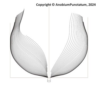
Eight years ago, I reconstructed the line plan of the Fly based on the original plans and drew a disposition of frames plan adapted to my model. Inspired by the build logs from dockattner and Giampy65, I started to check and revise my old drawingss at the beginning of November last year. When editing in CAD, I set the scale to 1 inch = 1 drawing unit.

I was able to complete this revision at the end of 2023.

As an example, I show you the disposition of frames plan and my control drawing for the derived frames.
Fly-001.jpg

Fly-002.jpg

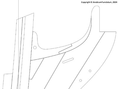
I then drew the backbone of the ship. As the arrangement of the components has not been handed down, I used the information provided by David Antscherl as a guide.

Fly-003.jpg

The components are now derived from the last drawing.
 
Hello Christian,
very nice project and I'm really pleased that you're tackling it. I've read about your plans in one or two reports/forums and am now all the more pleased that it's starting. The Swan Class books are high up on my wish list, unfortunately two volumes are sold out and I don't think they will be available any time soon. However, I will follow with interest.
On Jan 6 Amazon has a copy of Volume 1
 
@Herman Thank you for your interest.

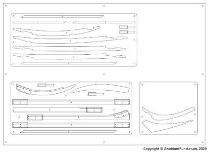
I will use my small CNC milling machine to "saw out" the components. Due to the very high accuracy, it is necessary to add appropriate tolerances, which are required later during assembly. In addition, the dimensions of the components must be reduced by 0.15mm for the caulking and by 0.1mm in all other cases. The gaps are required for the assembly and bonding of the components.

Fly-004.jpg

The components prepared in this way are arranged on boards of the appropriate thickness. These drawings are the basis for programming the CNC.
I still find it difficult to mill components on both sides, as is required for the keel and the deadwoods. The technique I tried on the Alert only worked to a limited extent or not accurately enough. I changed the procedure for building the Fly. The boards are fixed in a template made of MDF or plywood.

Fly-005.jpg

I actually wanted to finish the continuation of my report with the first woodwork. Unfortunately, as I was ill last week, you'll have to wait a little longer.
 
@Charlie1805, @Dubz Modelling World and all who pressed the Like Button
Thank‘s for you interest.

Charlie,
I will show a picture in the next update of my log. I own a CNC-Step with a milling area of 400x300mm.

Dirk,
the machine mills 100% perpendicular. That is the main advantage against a laser. A problem arises, if the working board is not parallel to the mill. That you have to fix, before you start to work on it. 16 mm plywood is not 16mm at all. After installation I mill the board, to get it parallel to the mill.
Another problem is the timber itself. I use prepared boards from Hobbymill. Sometimes they make a small curve. That is the reason, why I screw the timber on the working board.
 
Last edited:
@Charlie1805, @Dubz Modelling World and all who pressed the Like Button
Thank‘s for you interest.

Charlie,
I will show a picture in the next update of my log. I own a CNC-Step with a milling area of 400x300mm.

Dirk,
the machine mills 100% perpendicular. That is the main advantage against a laser. A problem arises, if the working board is not parallel to the mill. That you have to fix, before you start to work on it. 16 mm plywood is not 16mm at all. After installation I mill the board, to get it parallel to the mill.
Another problem is the timber itself. I use prepared boards from Hobbymill. Sometimes they make a small curve. That is the reason, why I screw the timber on the working board.
This is a very interesting post Christian. The tolerances are that precise!?!
 
This is a very interesting post Christian. The tolerances are that precise!?!

Paul, yes they are.
My CNC has an approach accuracy or repetition accuracy of 0.01 mm (1/100 mm). This is necessary to avoid steps on the finished part during milling.
The biggest deviations are caused by the influence of temperature and humidity on our preferred building material: wood, in my case boxwood.

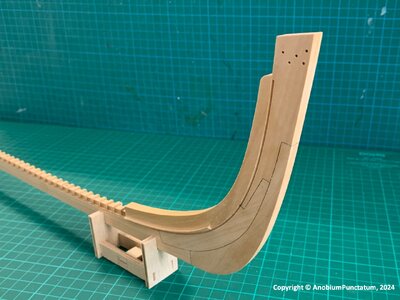
The tolerances given in the last part of my construction report were determined last year during the construction of my Alert.

Alert-Stem.jpg

The parts of the stem including the rabbet were milled and not further processed, with the exception of the rounded inner corners and the removal of the retaining bars, before gluing them together.
 
Paul, yes they are.
My CNC has an approach accuracy or repetition accuracy of 0.01 mm (1/100 mm). This is necessary to avoid steps on the finished part during milling.
The biggest deviations are caused by the influence of temperature and humidity on our preferred building material: wood, in my case boxwood.

The tolerances given in the last part of my construction report were determined last year during the construction of my Alert.

View attachment 419735

The parts of the stem including the rabbet were milled and not further processed, with the exception of the rounded inner corners and the removal of the retaining bars, before gluing them together.
Impressive. I spent a full day refining the joinery using a light box (though I was well-aware that the pieces were cut oversized). I'm sure Mr. Hunt did not go to the effort you did to create a favorable milling environment...
 
Impressive. I spent a full day refining the joinery using a light box (though I was well-aware that the pieces were cut oversized). I'm sure Mr. Hunt did not go to the effort you did to create a favorable milling environment...
Don't forget the one day for the refinement of your joints. I need more time to find my way with the mill. The big advantage of lilling the parts is, that it is easy to replace a part if something is broken. Another important point is, that I do not have to earn my money with my hobby.
 
Back
Top