

My second post...
Not really intending a full build log, but maybe people around the Great Lakes will be interested in our project. During an archaeological dig at the old Shickluna shipyard site in St. Catharines, Ontario, along the shore of the second Welland Canal, I became interested in the three masted schooners that were built to maximize their cargo capacity through the Canal and found that there are very few models and no drawings of the period to really portray those vessels. There were thousands of wooden schooners built, hundreds at the Shickluna yard alone. So my ship modeller brother suggested I do a set of drawings and he would build the hull. I was assigned masts and as much of the running rigging on them as possible.
He has built several POB models, Halifax, Rattlesnake, etc., but never a scratch build. I had never done a ship or model ship drawing, but I could see how they were done and I can do manual mechanical drafting. So, a lot of FOAK aspects, and we would do some things a bit differently next time. Of course!
I had seen drawings of a schooner online, and figured I only had to adapt them to make bulkhead and false keel drawings, but it turned out that the museum holding the drawing had moved recently and misplaced the drawing! After checking with several possible sources, collections and museums on the Lakes and striking out, I started a process of research and drawing development based on period photos, modern day shipwreck detailed reports, almost exclusively from the US side, and one or two academic theses.
I also was provided with a partial hull drawing, i.e. a hull body plan from an unknown (at the time) source of the St. Louis, a three-n-after canaller from the late 1870's , built at the Shickluna yard. Knowing from other records that the St. Louis was 128 ft long , after a few iterations and comparing the hull lines to period photos and rare shots of ships in drydock or still on the ways waiting to launch, we settled on lines that we thought would work.
We started with 1/96 scale, but settled on 1/72. The curve of the bilge on these things is quite tight and the larger size made rounding that a bit easier. So the hull is just under 22" long.
There were several interesting features that we had to research. For example, the bowsprit and/or jib booms of the ships were raised to about 45 degrees and the stern davits and catheads were hinged and flipped inboard to help to prevent fouling the lock gates as the ship rose or fell in the locks. So it ended up taking about 2-3 months to get a set of drawings that were adequate to build from. And changes were ongoing as better or more persuasive data came available.
To test the design, I first took the false keel and bulkhead drawings and made the parts out of 1/8" white foam board and mocked it up. Made a few tweaks, figured out how to incorporate a retractable centreboard, and how, from wrecks info, it had been hinged and controlled, and we started cutting wood.
I was never quite sure about the transom and counter under the stern -- a lot of curves there that are hard to represent in 2D (I don't know Autocad and wasn't going to buy and learn it for one project). So, I learned how to make a half hull to view it before we go too far into the hull construction. Made this 1:100, just to be a bit more manageable and frankly to be within the capacity of my scroll saw when it came to cutting the sheer line on the top layer of wood, as well as the bow and stern profiles. It turned out very, very well and it was a great aid to the model builder.
Rigging design research was a whole other project in itself. You can only see so much detail on old photographs, very few of which show deck and bulwark level rigging details, and shipwrecks generally don't have helpful amounts of rigging surviving.
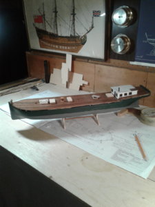
Here is a photo of where we are today. The model is sitting on my arrangement drawing as it happens, so you can get a glimpse of it. Not using CAD, and incorporating changes as we learned more, it is a good thing I used good quality vellum and still have my old erasing shield (for any old craftspeople in the crowd). I have all three masts made, with gaffs and booms, and the foremast and mainmast rigged as much as they can be before installation. Even figuring out what rake to give the masts took many hours. My brother has gotten this far in the hull. He is just checking where to put hatches, windlass, pawl post, etc. Note that bowsprit is articulated into the pawl or Samson post with a mortise and tenon arrangement that allowed it to pivot upwards in the canal. In the photo it is well aft of where it actually sits. This is just a snapshot. Bulwarks are going on now I think. Hull colour comes from research also. Leaden gray below and emerald green above. The deck cabin is for galley, captain, mate and cook quarters. Crew lived in the forecastle via a scuttle just aft of the windlass, keeping company with the anchor chain lockers.
I know this is a long post. I will post more if there is any interest as we go. And I see at the end of all this typing that the pdf photo is too big to post. I will work on that tomorrow. Meanwhile, here is a simplified pen and ink sketch of the ship to give you an idea...

Not really intending a full build log, but maybe people around the Great Lakes will be interested in our project. During an archaeological dig at the old Shickluna shipyard site in St. Catharines, Ontario, along the shore of the second Welland Canal, I became interested in the three masted schooners that were built to maximize their cargo capacity through the Canal and found that there are very few models and no drawings of the period to really portray those vessels. There were thousands of wooden schooners built, hundreds at the Shickluna yard alone. So my ship modeller brother suggested I do a set of drawings and he would build the hull. I was assigned masts and as much of the running rigging on them as possible.
He has built several POB models, Halifax, Rattlesnake, etc., but never a scratch build. I had never done a ship or model ship drawing, but I could see how they were done and I can do manual mechanical drafting. So, a lot of FOAK aspects, and we would do some things a bit differently next time. Of course!
I had seen drawings of a schooner online, and figured I only had to adapt them to make bulkhead and false keel drawings, but it turned out that the museum holding the drawing had moved recently and misplaced the drawing! After checking with several possible sources, collections and museums on the Lakes and striking out, I started a process of research and drawing development based on period photos, modern day shipwreck detailed reports, almost exclusively from the US side, and one or two academic theses.
I also was provided with a partial hull drawing, i.e. a hull body plan from an unknown (at the time) source of the St. Louis, a three-n-after canaller from the late 1870's , built at the Shickluna yard. Knowing from other records that the St. Louis was 128 ft long , after a few iterations and comparing the hull lines to period photos and rare shots of ships in drydock or still on the ways waiting to launch, we settled on lines that we thought would work.
We started with 1/96 scale, but settled on 1/72. The curve of the bilge on these things is quite tight and the larger size made rounding that a bit easier. So the hull is just under 22" long.
There were several interesting features that we had to research. For example, the bowsprit and/or jib booms of the ships were raised to about 45 degrees and the stern davits and catheads were hinged and flipped inboard to help to prevent fouling the lock gates as the ship rose or fell in the locks. So it ended up taking about 2-3 months to get a set of drawings that were adequate to build from. And changes were ongoing as better or more persuasive data came available.
To test the design, I first took the false keel and bulkhead drawings and made the parts out of 1/8" white foam board and mocked it up. Made a few tweaks, figured out how to incorporate a retractable centreboard, and how, from wrecks info, it had been hinged and controlled, and we started cutting wood.
I was never quite sure about the transom and counter under the stern -- a lot of curves there that are hard to represent in 2D (I don't know Autocad and wasn't going to buy and learn it for one project). So, I learned how to make a half hull to view it before we go too far into the hull construction. Made this 1:100, just to be a bit more manageable and frankly to be within the capacity of my scroll saw when it came to cutting the sheer line on the top layer of wood, as well as the bow and stern profiles. It turned out very, very well and it was a great aid to the model builder.
Rigging design research was a whole other project in itself. You can only see so much detail on old photographs, very few of which show deck and bulwark level rigging details, and shipwrecks generally don't have helpful amounts of rigging surviving.
Here is a photo of where we are today. The model is sitting on my arrangement drawing as it happens, so you can get a glimpse of it. Not using CAD, and incorporating changes as we learned more, it is a good thing I used good quality vellum and still have my old erasing shield (for any old craftspeople in the crowd). I have all three masts made, with gaffs and booms, and the foremast and mainmast rigged as much as they can be before installation. Even figuring out what rake to give the masts took many hours. My brother has gotten this far in the hull. He is just checking where to put hatches, windlass, pawl post, etc. Note that bowsprit is articulated into the pawl or Samson post with a mortise and tenon arrangement that allowed it to pivot upwards in the canal. In the photo it is well aft of where it actually sits. This is just a snapshot. Bulwarks are going on now I think. Hull colour comes from research also. Leaden gray below and emerald green above. The deck cabin is for galley, captain, mate and cook quarters. Crew lived in the forecastle via a scuttle just aft of the windlass, keeping company with the anchor chain lockers.
I know this is a long post. I will post more if there is any interest as we go. And I see at the end of all this typing that the pdf photo is too big to post. I will work on that tomorrow. Meanwhile, here is a simplified pen and ink sketch of the ship to give you an idea...
Attachments
Last edited:


