FLYING DUTCHMAN

PLANKING 3A

FD1-72-03-01.jpg
Last time, I stuck the partition wall on the front side, glued the keel, and put the side reference
line with a pencil to finish.
This time I stuck the outer skin of the hips. After this, the outer plate was cut neatly to match
the outline of the stern.


FD1-72-03-02.jpg
This is a picture taken from behind diagonally before cutting it neatly.
The outer plate is pasted from the red arrow part.


FD1-72-03-03.jpg
Stick 2 mm thick and 4 mm wide cypress into the red arrow and stick it up with that as a reference.
I use 4mm width, 3mm width, and 2mm width cypress according to the place.
But the main width is 3mm.


FD1-72-03-04.jpg
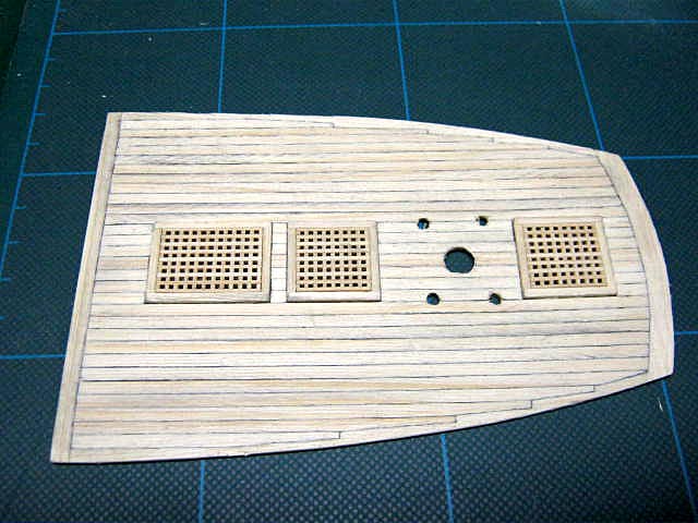
Enlarged photo of the stern part.
The part of the groove is 2mm wide and 1mm thick cypress. If you stick a 2mm thick material on this,
it will pop out by 1mm.
Two pieces of 4mm width are stuck on it.


FD1-72-03-05.jpg
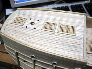
Enlarged photo of the side of the ship.


FD1-72-03-06.jpg
Enlarged photo of the bow.
After this, I will paste it on top.


FD1-72-03-07.jpg

FD1-72-03-08.jpg
I could stick the outer plate of the bow part, port and starboard somehow. I have to move it
to the left and right at the same time.


FD1-72-03-09.jpg

FD1-72-03-10.jpg
I will stick the outer plate of the stern part, the port and starboard.


FD1-72-03-11.jpg

FD1-72-03-12.jpg
I also pasted the stern part to the top!


FD1-72-03-13.jpg
After that it is pasting from the waterline to the bottom part.


FD1-72-03-14.jpg
FD1-72-03-15.jpg
I stuck it on the bottom of the water line and managed to get to this point.
I have a little more.
Is it about 2 pieces of 3mm wide cypress?


FD1-72-03-16.jpg
FD1-72-03-17.jpg
I've finally pasted it.
There were days when I couldn't paste it, so I was a little dissatisfied.
When pasted up, the outer plate is rattling.
Is there any trick to put it neatly?
Even if you stick it carefully, there will be gaps and there will be steps, so it will be a problem.
After this, sandpaper is applied.
Also, the edge of the protruding material is cut cleanly.


FD1-72-03-18.jpg
I scraped it with an electric sander for about 2 hours.
The hull was somehow clean, so I cut off the edge of the outer skin.
Then, the pillars of the frame were cut off and sandpaper was applied to the inner wall.
I attached the stem part of the bow with epoxy adhesive and tightened it firmly with screws.


FD1-72-03-19.jpg
I temporarily assembled a beak head on the stem of the bow.
The stem is grooved so I just inserted the beakhead.
Have you seen the whole picture?


FD1-72-03-20.jpg
This is a close-up photo of Beekhead.
 
GUN PORTS 4A


FD1-72-04-01.jpg
The position of the gunport skid was drawn on the hull from the side view of the work drawn on
the 4mm cena veneer, and the gunport of the upper deck was opened.
I took a photo while I was opening it so I will take the gunport work on the lower deck seriously.


FD1-72-04-02.jpg
Use this router to open the gun port below (the mouth of your face).
I opened the upper gun port by the same work.


FD1-72-04-03.jpg
First, make a lot of small holes with a router.


FD1-72-04-04.jpg
Then, cut with a design knife.


FD1-72-04-05.jpg
It looks like this. After this, I finished it nicely with a file.


FD1-72-04-06.jpg
It is in a finished state.


FD1-72-04-07.jpg
It is a work under the engraved part of the surprised face.
Since the face is made with putty or wood powder clay, the face is traced down to the
extent that you only need to know the size.
First, cut out the mouth of the paper with a surprised face printed on it, put it on
the gun port of the hull, and fasten with masking tape.


FD1-72-04-08.jpg
Put carbon paper under the printed paper and trace down your face with a stylus.


FD1-72-04-09.jpg
I'm a left-handed person, so I take a pencil with my left hand and a camera with my right hand.


FD1-72-04-10.jpg
End of port trace.


FD1-72-04-11.jpg
Then, the starboard trace is finished.
 
FD1-72-04-12.jpg
Here, I will make the outer panel.
This self-made tool is made by cutting a saw blade and attaching a handle.


FD1-72-04-13.jpg
It is the expansion of the blade.
This will scratch the outer plate and add wood grain.
I will scratch from the bow toward the stern.


FD1-72-04-14.jpg
I will scratch like this.


FD1-72-04-15 (1).jpg
The surface fluffs like this.


FD1-72-04-16.jpg
So I bought a stainless steel scourer.
This evenly rubs the outer skin of the hull.


FD1-72-04-17.jpg
Large fluffs have fallen off.
Is it okay if I can get the details?
I don't mind.
That would be more like FD.


FD1-72-04-18.jpg
The starboard side, the red arrow part is a 1 x 4 x 900 mm cypress wood glued to the main wale.


FD1-72-04-19.jpg
Similarly, on the port side, the main wale part indicated by the red arrow is bonded.


FD1-72-04-20.jpg
The bow is taken from the front.
It seems that the main well can be attached to the left and right objects.
As always, work on the left and right is nervous. (=゚ω゚) no


FD1-72-04-21.jpg
The starboard side, the red arrow part is a 2 x 2 x 900 mm cypress wood and the third
rail part from the top is glued.


FD1-72-04-22.jpg
Similarly, on the port side, glue the third rail part from the top.


FD1-72-04-23.jpg
FD1-72-04-24.jpgFD1-72-04-25.jpg
FD1-72-04-26.jpg
Next, glue the first and second rails from the top.
When sticking the outer plate, decide the main wale position and rail position from the
side view for work drawn on the china veneer, and if you stick the outer plate material
that matches the width of the main wale rail, the main wale rail to be stuck on it It
will be easier to paste.
This time, for the main wale, we stuck the same 2 mm thickness as the outer plate material,
and stuck the 1 mm thick main wale on it.

If you stick 1mm thick material for the rail and lower it by 1mm lower than the outer plate material,
and then paste the 2mm thick rail material, it will be a rail that protrudes 1mm from the outer plate,
and you can paste it neatly.
 
another interesting technique used by Mellpapa is to texture the surface of the planking.

This is in total reverse of some model builders who sand the surface of planking to almost a glass smooth surface. What Mellpapa did was to give the wood a weathered worn look.
 
vertical skids 5A


FD1-72-05-001.jpg
It is pasting of the vertical skid part next to the gun port.
Hot water is contained in a small bottle, and when the skid cypress is added here to soften it,
use the large bottle next to it to add a rounded habit and blend it into the hull.
Engrave the combination with the horizontal molding and glue it with an instant adhesive
for woodworking (made by Daiso) before the cypress wood dries.


FD1-72-05-002.jpg
The red arrow on the port side is the pasted skid part.
Finally I pasted six.
There are 10 in total.
(';Ω;`) Woo...


FD1-72-05-003.jpg
This is the starboard side.
Simultaneous paste write the same place of the two broadside because the body is
pasted same six with the port side.


FD1-72-05-004.jpg
Looking up, it looks like this.


FD1-72-05-005.jpg
I finally pasted 10 on the port side.


FD1-72-05-006.jpg
I also stuck 10 on the starboard side.
About the same position.
It's subtle though. (^ω^)b
 
GUNPORTS 5A


FD1-72-05-007.jpg
I'll make a box to line the scary face of Gunport.
A lot of 13mm x 13mm x 2mm boards on the left side of the photo...
Lots of 15mm x 15mm x 2mm boards on the right side...
I cut this board from the board sold at Daiso. Since it is a box that is attached
from the inside of the hull, cheap materials are sufficient. It's not something you can see.
(^ω^)b


FD1-72-05-008.jpg
First, glue the board to the L shape.


FD1-72-05-009.jpg
Adhesive by combining two L-shaped adhesive plates.


FD1-72-05-010.jpg
So it's a close-up image though it doesn't mean much.


FD1-72-05-011.jpg
Box-shaped by sticking the bottom with a 15 mm × 15 mm plate material.


FD1-72-05-012.jpg
So it's an up image. The tight bond of the adhesive is protruding.
The adhesive is dry.


FD1-72-05-013.jpg
When the adhesive dries, fill the inside with Mr.COLOR's matte black.


FD1-72-05-014.jpg
I filled the inside with everything.
Since it is not dry yet, it cannot be bonded to the hull yet.


FD1-72-05-015.jpg
While the gunport lining box is being dried, make the gunport trim on the hull.
Using an Evergreen 1.6mm rod, wrap it around a jig that combines a round bar and
square timber and clip it. Soak it in boiling water for about 1 minute and then rinse with water.


FD1-72-05-016.jpg
Then, it's already watered!


FD1-72-05-017.jpg
Cut with a nipper!


FD1-72-05-018.jpg
Then, bond like this.


FD1-72-05-019.jpg
Don't glue it.


FD1-72-05-020.jpg
Starboard, bonding completed!


FD1-72-05-021.jpg
Bonding on the port side is also complete.


FD1-72-05-022.jpg
Once the adhesive was dry, I added a mold with a tool with a scribing on the skin.


FD1-72-05-023.jpg
Glue the handle that can be grasped with tweezers to the back of the gun port lining box.


FD1-72-05-024.jpg
Glue to the back of the gun port as indicated by the red arrow.
Once you have glued the deck, you can't touch it again, so attach a
lot of tight bonds and stick firmly.
 
It is a continuation from the previous.


FD1-72-06-001 (1).jpg
It's pasting the box for lining the gun port, but I cut it according to
the curves on both sides of the hull.
I forgot to write it the last time.


FD1-72-06-002.jpg
Finally the installation of the lining box is completed!


FD1-72-06-003.jpg
It is a close-up image of the bow side.


FD1-72-06-004.jpg
This is also an up image.
I forgot to shoot the stern.
Tohoho...
 
THE DECK


FD1-72-06-007.jpg
A piece of aviation veneer.
It is a scrap that came out when used as a support plate for the outer plate.
This will be the lower deck material.


FD1-72-06-008.jpg
This is the drawing of the deck.
I will print it out and cut it out to fit the hull.


FD1-72-06-009.jpg
It fits nicely.
Trace down this drawing to a piece of aviation veneer and cut it out.


FD1-72-06-010.jpg
A 0.6mm thick aviation veneer is cut out.


FD1-72-06-011.jpg
When the cut-out deck lower plate material is fitted to the hull...
Well, it looks like this.
It is perfect.
With this, the deck material can be put in, but before that, it is easier to
stick the deck material by working the grating main mast fife rail etc. according to the lower deck material.
Therefore, I will first work on the grating and main fist rails.
 
Crafting of grating


FD1-72-06-012.jpg
About 70 pieces of 1x2x900mm cypress wood cut to 70mm are prepared.
that? What is the prototype of this chopper? ?
I forgot (lol)


FD1-72-06-013.jpg
Align the cut materials with a jig.


FD1-72-06-014.jpg
Adhere only the both ends of the aligned material, the red frame part.


FD1-72-06-015.jpg
Back with masking tape.


FD1-72-06-016.jpg
Grooves will be carved with Proxon's "Grating work slide table (self-made)"
for mini circular saws.
●Experiment 001 ● I am making a "grating work slide table" with grating.
I'm working on the grating here as well.


FD1-72-06-017.jpg
Engrave the first groove to fit the guide bar of the slide table.
Match the groove that was carved first with the bar of the guide and carve the second groove.
After that, the groove is carved by repeating this.


FD1-72-06-018.jpg
The groove is finished.
It's like a washboard.


FD1-72-06-019.jpg
Mark only one.
It is necessary because we will let you know the direction when incorporating it.


FD1-72-06-020.jpg
Separate the washboards, align the ones marked with magic, and assemble them vertically and horizontally.


FD1-72-06-021.jpg
I incorporated as much as I needed.


FD1-72-06-022.jpg
Dilute the woodworking bond with water and soak the grating created in it.


FD1-72-06-023.jpg
It doesn't mean much, but it is a close-up image of Dobu-zuke.
Absorb plenty of woodworking bond aqueous solution.


FD1-72-06-024.jpg
Wipe off excess water and let it dry overnight.


FD1-72-06-025.jpg
Clean it with sandpaper and cut the margins to fit the size.
The rest is to make a frame for this.


FD1-72-06-027.jpg
Tight bond adhesion with the largest frame of grating.


FD1-72-06-028.jpg
When the tight bond is dry, cut off the protruding part.


FD1-72-06-029.jpg
Gluing the grating receiver inside the frame. Otherwise the height will not fit.


FD1-72-06-030.jpg
Fit the three gratings into the frame.
Ummm... this is...


FD1-72-06-031.jpg
Next is the creation of a medium graching frame.
The combination is done like this. I forgot to take a photo when I made a big frame.


FD1-72-06-032.jpg
After bonding, cut the protruding part. After this I also made a small grating frame.


FD1-72-06-033.jpg
I will put it on the lower deck material. It almost matches. It looks like this.


FD1-72-06-034.jpg
I got tired of doing all the grating work, so I decided to do something else.
I cut the broken bowsprit attached to the bow of the Flying Dutchman from a round bar.
Adjust the shape to meet the drawing, and cut the root to fit the attachment part of the bow.


FD1-72-06-035.jpg
I installed it.
It looks like this.


FD1-72-06-036.jpg
I had a bow split, so I shot the whole picture.
Is it getting more and more like that? ?
This time we are working on fife rails, but this is it for today.
 
Fai rail and bit work


FD1-72-07-01.jpg
Build the main mast bit and fie rail. I searched for a 4mm square timber for bits,
but I don't have it on hand.
Then, when I went to buy it at a home center... I have already stopped handling cypress wood for work...
I wonder if the two home centers that were handling cypress wood for work have also stopped...( ; ∀;)b
Wherever I live, I no longer have access to cypress wood. You have to buy it online...
So, I will make a bit by sticking 2 x 4 mm materials with the materials I have.


FD1-72-07-02.jpg
I cut out a 2 x 4 mm piece of wood with my hand.
It doesn't mean much, but it's a close-up photo.


FD1-72-07-03.jpg
Then, first of all, the necessary four pieces of material are pasted together.
Tight bond is used as the adhesive.


FD1-72-07-04.jpg
Drill holes for belay pins using 1mm thick and 3mm wide material for fife rails.


FD1-72-07-05.jpg
The diameter of the hole is 0.8mm.


FD1-72-07-06.jpg
I will combine bits and fife rails.


FD1-72-07-07.jpg
And it's done.


Deck attachment


FD1-72-07-08.jpg

When sticking the deck, the workable parts were made first. What is a long stick?
Although it is a board for margin plank, even if it is made, the deck here cannot
see the margin plank parts on the port and starboard sides.
Let's practice margin plank here for the time being. (;^ω^)b


FD1-72-07-09.jpg
Tight bond is applied to the adhesive part to attach the lower deck.


FD1-72-07-10.jpg
I have a tight bond like this.


FD1-72-07-11.jpg
Then, the lower deck material is glued.
The frame of the deck part has a loose R, the middle part is slightly higher,
the center keel part has a loose shear line, and the bow and stern sides are slightly higher.
So, fix the important parts with pins until the tight bond dries. (;^ω^)b


FD1-72-07-12.jpg
Margin plank parts on the port and starboard sides were pasted, and deck materials near the bow were pasted.
I painted the grating part of the lower deck material with matte black.


FD1-72-07-13.jpg
This is a close-up photo of the grating part.
That's all for today. I can't concentrate on the model because
I have to change the engine oil of the snow blower, adjust the accelerator, remove the snow, and so on.
……Deck attachment is still ongoing……(´▽`)b
 
Continued decking


FD1-72-08-01.jpg
Eh, it's a continuation of pasting the deck from the last time. I'm working on it,
but I'm not sure if I take a picture because the color of the lower deck material
and the color of the deck material (cypress) are similar...(;^ω^)b


FD1-72-08-02.jpg
The mellpapa chopper is very useful for cutting the same length of material.
It's easy because you don't have to modify the cut after you cut it.


FD1-72-08-03.jpg
The edges of the deck material are painted with a pencil. The pencil is 6B thick.


FD1-72-08-04.jpg
I took a picture of my work bench landscape. I work in front of the liquid crystal
display of my computer. In front of you, you can see the MONO eraser. Next to that
is a face brush, with this brush a tight bond is applied to the back of the deck material
and attached to the lower deck of the deck. Tight bond is in a small bottle next to the brush, Mr. COLOR.
There is water in the big bottle above the brush and I use it for brush washing.
The deck material that has been trimmed is placed next to the chopper.
Well, I'm working on it like this.


FD1-72-08-05.jpg
Since the edges of the deck material are painted with a pencil, the hands naturally become dirty like this.
This is the right finger.


FD1-72-08-06.jpg
This is your left finger...
When both hands are so dirty, I wash my hands immediately, clean them, and then work again,
but they get dirty soon.


FD1-72-08-07.jpg
Somehow it's pasted here. As usual, the color of the deck material and the color of the
lower board are similar, so I don't know unless I look closely.


FD1-72-08-08.jpg
The FISKARS design knife I bought recently, this handle is very easy to hold,
and my fingers won't hurt even if I put my effort into it. The handle has an isosceles
triangle with a loose cross section, and the material is soft enough to fit your fingers.
The blade I came with when I bought it is A , and it's a bit hard for me to use,
so I'm using the blade of C 's Olfer art knife.
However, it will not fit if it is as it is, so I use it by grinding the opposite side
of the blade and the buttocks with a grinder like B.
The part that holds the blade on the body side of FISKARS is also deeply cut with a piranha saw.


FD1-72-08-09.jpg
It looks like this when you put on a cap.
It was a tool that fits in my hand after a long time.
I like it so I think I should buy another one.


FD1-72-08-10.jpg
So I managed to finish attaching the deck. The grating part is not glued yet.
It's a hindrance to put sandpaper.


FD1-72-08-11.jpg
Stick the inner wall on the left and right sides using wooden clothespins.
The wooden clothespin was bought at a 100 yen shop.
But it looks a little strange.
Mufufu (;^ω^)b


FD1-72-08-12.jpg
The state above is when I bought it. With this, I can not pinch it with the tip,
so I attached the wooden parts in reverse and used it under the photo.
You can sandwich it with the other person.
I used it on a blog somewhere like this. Great person who thought this!


FD1-72-08-14.jpg
So, work on the left and right at the same time.


FD1-72-08-15.jpg
I managed to paste the center of the hull.


FD1-72-08-16.jpg
This time, I will proceed with the work towards the stern.
But this time, this is it.

Well, that’s all for today. It is the start of snow removal in front of the garage
that has become a snowdrift from now on... ('▽ `)b
 
FD1-72-09-01.jpg
I finished pasting the inner wall of the hull.
Since I put a 2 mm thick cypress, I couldn't rely on it.


FD1-72-09-02.jpg
It is the bow side part. The cypress wood stuck inside is protruding.


FD1-72-09-03.jpg
It is the middle part of the ship.


FD1-72-09-04.jpg
And here is a close-up photo of the stern.
After sanding the inside, cut off the protruding material.


FD1-72-09-07.jpg
After sanding the inside, I scratched the surface with a scratching tool.


FD1-72-09-06.jpg
After that, I did not cut the protruding material on the inner wall yet,
but I glued the fife rail I made earlier.


FD1-72-09-08.jpg
The first scratching tool cracked while I was using it, and the tip flew somewhere.

FD1-72-09-09.jpg
It's a close up. It's been brilliantly broken. I used to apply it to my body and healed the curve,
but at last I died.


FD1-72-09-10.jpg

FD1-72-09-11.jpg
So, this is the one I made again.


FD1-72-09-12.jpg
The blade is up. I made it by cutting the tip of the piranha saw below.


FD1-72-09-13.jpg
When I finish attaching the outer panel and attach the gun deck, I feel relieved...
Then I got tired of making FD...
I wanted to make something different, so I made about two choppers.
Last year, the Asahikawa Model Club members asked us to make it, and we made about five.
At that time, I purchased a lot of materials, so it is production with inventory management
of the materials.
I would like to take it to a model exhibition in Sapporo in the summer and sell it if there
is someone who wants it.
Is anyone really going to use this tool? ?

That's all for today. It was raining today on March 7th. Thanks to this, the tires slip... (´▽`)b
 
Last edited:
PART 10A


FD1-72-10-01.jpgFD1-72-10-02.jpg
Cut out the material that popped out of the inner wall
Since the lead of the mechanical pencil, 0,5 mm, is gone, I went to a stationery store
near my workplace to buy it...
What? A lot of nostalgic things...

Higomori is placed in the place where a cutter knife or a design knife is displayed..
I thought that it was already destroyed with a Bonknife / Cutter knife .I know if the Bonknife is placed ...

About 6 on the display rack... The price is 320 yen

There are five "Registered Munechika Higo Knife" in front of the photo, and one
"Registered Trademark Higo Mamoru Sadama (large)" in the back.

I bought one at a time.

Where did the Higomori that I had when I was a kid go to...

The only thing I could bring to elementary school was the Bonn knife, which was sold for
about 10 yen at that time... I wonder if Higomori cost about 150-200 yen...

Mamoru Higo used to build at home.

You played an active part by cutting trees.

Immediately, I tried to scrape the protruding inner wall material with Higomori.
The Higomori blade is attached to the right-handed person.

In my case, since it is left-handed, the blade will always face the body.

So my parents often warned me.

"Blade of the knife, toward the outside of the body Take Ke."

However, since I have a knife in my left hand, it's better to point the blade here.


FD1-72-10-03.jpg
So, the cutting of the inner wall material that popped out without cutting hands was completed.
Mr. "Higo Mamoru", it was very nice.


FD1-72-10-04.jpg
After I finished the above work, I got a job to draw a picture... It's a free service, but it took
a long time.
During that time, the production of FD was temporarily stopped.

Even after my painting job was over, I took it off for a while.

I'm tired of drawing...

What kind of picture did you draw? A bird's-eye view of the building (sports facility)
and illustrations of the internal facilities in use.

Then, I finally returned to FD and made drawings of the bow deck.


FD1-72-10-05.jpg
Trace down the lower plate of the bow deck using the remaining part of the 0.6 mm thick aviation veneer,
which is the support plate on the side of FD.


FD1-72-10-07.jpg
Tracedown has finished.
I used black carbon paper and iron brush. That's the way you always do it.


FD1-72-10-09.jpg
I tried shooting up the tracedown.
Cut this out.


FD1-72-10-08.jpg
It was cut out using a cutter knife and a design knife.


FD1-72-10-10.jpg
Then, it is a temporary assembly.
There is a white and round bow, but it is just a pushpin.
I'm temporarily fixing this.
Sandpaper both sides and the front part to fit the hull.


FD1-72-10-11.jpg
I will stick 1mm thick cypress wood around the bottom plate that fits the hull.
Once the adhesive dries, assemble it further.
Once it fits into the hull, the deck material is attached.


FD1-72-10-12.jpg
Oops! !!
A spring that makes the red circle part a grating before pasting the deck material.


FD1-72-10-13.jpg
It is a craft of grating.
For more information


FD1-72-10-14.jpg
I incorporated three red circles for grating.


FD1-72-10-15.jpg
Prepare a tight bond diluted with water in a paint dish.


FD1-72-10-16.jpg
Grate the 3 pieces of grating in a water-diluted tight bond and let them absorb plenty...


FD1-72-10-17.jpg
Excess water is sucked into the tissue.


FD1-72-10-18.jpg
Leave it as it is and let it dry overnight.


FD1-72-10-19.jpg
Prepare the deck material.
Cut the cypress 1mm thick 3mm width 13cm in length with the right angle chopper as necessary.

Right angle chopper is useful in such a case... (;^ω^)b
 
Last edited:
Yes and they are just plain out fun to read and enjoy.


i think what happened is the hobby started to get way to serious. Builders were being very critical with every historical detail, craftsmanship and research had to be of a high level, building has to have every timber perfect and so on. It got to the point even milled wood was criticized for being .005 thousandths off and there were sanding marks from 100 grit sanding paper.
This form of model building is ok it's just another style, problem is 95% of builders in the hobby do not built this way. The bar was set to high and this style sucked the fun right out of the hobby.
Mellpapa restored the "fun" and creativity back in the hobby. He shows us we can use different materials and techniques.
 
It is a continuation of the grating work on the bow deck. part 11A


FD1-72-11-01.jpg

I will cut the left and right.


FD1-72-11-02.jpg
After finishing the left and right trimming, apply sand pepper to remove the unevenness...
It is cut according to the drawing, but it does not quite follow the drawing.
So it's a close cut.


FD1-72-11-03.jpg
It is expansion.
Although it is still marked with magic, in the end we will paint the FD No. so we will proceed as it is.


FD1-72-11-04.jpg
Creating a frame for grating.
I'm using a 2mm square bar.


FD1-72-11-05.jpg
It looks like this when enlarged.


FD1-72-11-06.jpg
Then, cut the frame material that popped out in the chopper prototype.
There are various prototypes of the chopper, so I have to use it...

FD1-72-11-07.jpg
I took a close-up shot.
Since it is a single-edged blade, it can be cut cleanly by applying it to a flat blade.
There is no need to correct the cut.


FD1-72-11-08.jpg
I set the grating on the lower deck of the deck where the frame had been pasted,
and pasted two deck materials.


FD1-72-11-09.jpg
The grating frame isn't glued yet.
As shown in the picture.


FD1-72-11-10.jpg
I will stick two deck materials first and paste them from the left and right,
and I will stick the deck materials around the gratin.


FD1-72-11-11.jpg
Finally, if you attach only the arrow part with a red circle, the bow deck is over...


FD1-72-11-12.jpg
I managed to finish pasting.


FD1-72-11-13.jpg
Remove the grating and file.


FD1-72-11-14.jpg
After applying sandpaper, I put a grain of wood on it and scraped off the fluff
with a stainless steel scrubber.


FD1-72-11-15.jpg

FD1-72-11-16.jpg
The grain is like this.


FD1-72-11-17.jpg
I drilled a hole for the fore mast and a bit hole in the fife rail.
Then glue the grating with a tight bond.


FD1-72-11-18.jpg

Completion of the bow deck


.
FD1-72-11-19.jpg

Immediately, I tried to temporarily assemble it on the hull. It looks like this. It took quite a while.
I'm glad that the grating was beautiful as it is.


FD1-72-11-20.jpg
It looks like this. It took quite a while. I'm glad that the grating was beautiful as it is.
This time, we will not plug the nails on the deck.
I did it with 1/72 BP, but I could not see it at all when it was dirty and painted.
Since the FD is also stained and painted, it would be a waste of time to reproduce the invisible wooden plug.
Now, next is the deck work on the stern side.
 

Attachments

  • FD1-72-11-18.jpg
    FD1-72-11-18.jpg
    50.5 KB · Views: 3
  • FD1-72-11-19.jpg
    FD1-72-11-19.jpg
    54 KB · Views: 1
Stern deck work part 12A


FD1-72-12-01.jpg
It is a drawing of the deck of the stern. I will trace this down to a 0.6mm airline veneer.
Use the usual carbon paper and iron brush, triangle ruler, straight ruler.


FD1-72-12-02.jpg
Then, trace down immediately.
I used an extra 0.6mm aviation veneer.
I bought Aviation Veneer at Tokyu Hands when I went to Sapporo.
We are out of stock now and are back in stock.
So when I went to Sapporo, I stopped by Hands, ordered it, and received it when it arrived.


FD1-72-12-03.jpg
It was cut out with a cutter and a design knife.
If you can do this, there is one thing to do...


FD1-72-12-04.jpg
I will just apply sandpaper according to the hull and make sure the temporary assembly fits exactly.


FD1-72-12-05.jpg
Work on three stern decks simultaneously.
When the temporary assembly fits perfectly, attach a reinforcing plate to the back side.
It's lined so as not to be distorted.
At that time, attach a camper and line it up.


FD1-72-12-06.jpg
Stick the edges around the three decks. It is the margin plank part.
It's 1/72, so it's small, so I don't have to do this, but when I draw a deck drawing,
I'm drawing a margin plank...
So, the FD issue actually looks like this... I can't see it in the movie, so I guess...


FD1-72-12-07.jpg
I shot each margin plank up, so I will post it.
Stern deck 001


FD1-72-12-08.jpg
Stern deck 002


FD1-72-12-09.jpg
Stern deck 003


FD1-72-12-10.jpg
After pasting the margin plank, we will further assemble it with the hull.
When this is over, I'm pasting the deck material...
This is the next one
 
Back
Top