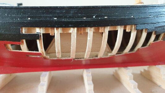
Emma C. Berry 1:32 PoF by Model Shipways

The book is The Restoration of the Smack Emma C. Berry at Mystic Seaport 1969-1971, by Willits D. Ansel, originally published by the Marine Historical Association, Mystic, CT in 1973. ISBN 0-913372-08-0.

It was reissued around 1990, I think, but has been out of print since 1995.

Fred
Thanks I found a copy online for sale at reasonable cost.
 
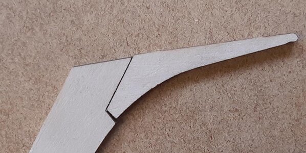
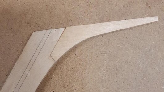
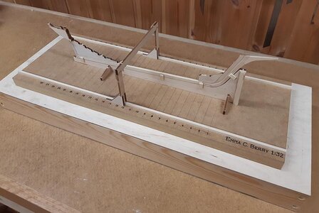
The backbone is made from eight pieces, all laser-cut. The keel and stern deadwood are all in one, the stem and apron in another, with separate head knee, forward deadwood and sternpost. The horn timber and rudder trunk are three more pieces. The fit is reasonable in most cases, although the head knee is not very good. I made a new one, both to get a better fit, and to leave room for a separate billethead in boxwood, so I can test my micro-carving skills. There is an odd kit design choice here, with the little skeg under the rudder post part of the sternpost, which butts against the after end of the keel. This is not only structurally incorrect (the sternpost should be stepped on top of the keel) and weak (cross grain), but creates unnecessary difficulty. The after face of the sternpost is hollowed to allow a snug fit for the rudder post. Without the skeg, this can be done easily with a round file. So I broke the skeg off, and replaced it later with a piece scarfed into the bottom of the keel. I also made a separate keel, after I discovered that the joint as provided does not give the right rake for the stem.

As it turns out, the strongback profile does not have the same stem rake as the plans or the laser cut pieces, probably due to cross-grain shrinkage of the strongback (this problem reappears later for other parts). No big worry, I can pack out the strongback to fit.

Berry 4-1 comp.jpgBerry 4-2 comp.jpgBerry 4-3 comp.jpgBerry 4-6 comp.jpg

The rabbet has to be cut by hand. The location is clearly indicated on the plans, and the angle of the rabbet at several locations is shown. The model is just big enough that one can cut an accurate rabbet, and the process is helped by the boat’s construction. For about half the length, the rabbet is simply a bevel on the upper edge of the keel, becoming a carved groove only at the stem and over the deadwood. Berry was built with a skeg (typical for a lot of fishing boat types in New England), so that the rabbet does not follow the keel all the way to the sternpost. The skeg is built up on top of the keel from stacked timbers, effectively providing a blade projecting below the planked part of the hull.

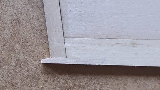
I started cutting the rabbet the same way I would on a full-sized boat, laying out the lines that define the edges and then cutting short guide sections where the plans provide accurate angle data. I made a short length of plank, square at one end and angled at the other, to test the depth and angle of the rabbet. I discovered that the rabbet could be easily cut with a sharp knife, and so gave up on the short segments and made long, sweeping cuts instead, which gave a smoother surface and fair curve.

This is one place where I miss a set of conventional lines, from which the bevels of the rabbet can be taken directly. The representation on the plans is only schematic, and does not really take into account how the width of the rabbet changes with the changing angle. I used the outer rabbet line as the guide, and then adjusted the bearding line as necessary to get the correct angles. This makes the rabbet wider on the stem than the plans show, and narrower across the skeg.

Berry 4-7 comp.jpg

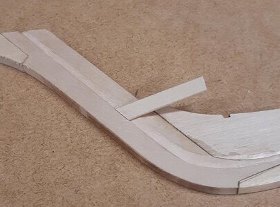
Once the rabbet was cleaned up (it will get some small adjustments during planking), the horn timber and rudder box assembly could be added to the head of the sternpost. This goes together smoothly and aligns readily. It has also shrunk slightly across the grain relative to the plans, but this can be accommodated. With that, the backbone is done, and framing can start.

Berry 5-2 comp.jpg
 
Very good description of your very good work
You have definitely everything under control :cool:
 
Hi Paul, nice model of Emma!. I see you went with the open planking on one side. Did that give you any headaches in keeping the sides aligned while planking?

Fred
 
Hi Paul, nice model of Emma!. I see you went with the open planking on one side. Did that give you any headaches in keeping the sides aligned while planking?

Fred
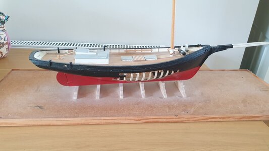
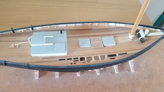
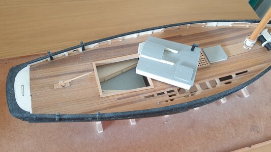
Hi Fred, From what I remember I used full planks but did not glue where I wanted the opening, then later cut it away.
 
I recently started a new build, and saw that there was not yet a log for this kit here (although a number of forum members seem to have built it), so decided to chronicle my progress. Afraid that I had already started a few things before I decided to record the process, so the first few photos are “re-enactments”.

The kit is Model Shipways’ Emma C. Berry in 3/8” scale (1:32), which recreates in miniature a sloop-rigged well smack built in 1866 in Noank, Connecticut. The vessel survived over a century of use as a fishing boat, coaster and yacht, going through numerous changes of rig, accommodation and configuration before being donated to Mystic Seaport Museum. There it was restored twice, and is now on display as part of the floating collection. The vessel is a favorite with the museum’s visitors, and Mystic Seaport assisted in the development of the kit, which shows the vessel as it was after its second restoration in 1992.

Construction is plank on frame with a high level of detail. The kit contains sheets of laser-cut parts in three thicknesses, a comprehensive wood package (strip, square, and round), a small set of britannia metal cast fittings, brass pins, eyebolts, rings and belaying pins, brass strip and wire, copper chain, wood blocks and deadeyes, six cards of rigging cord in two colors, and decals for the stern and scrollboard decorations. All of the wood parts are solid, even-grained basswood (no plywood or mdf). Four sheets of plans (by Ben Lankford) include drawings of all of the laser-cut parts, a hull construction drawing, a deck arrangement drawing, and a rigging plan, but no conventional lines drawing (one can be extrapolated from the frame shapes and other drawings). A 38-page instruction book contains more sketches and photos. It includes a brief introduction to the process of modelling (it assumes no prior knowledge), some of the traditional tutorial material (how to scribe a waterline, etc.), before taking the builder through the construction process in sufficient detail to get a decent result.

The drawings and material allow the construction of an interior, which is conjectural, and the structure of the model follows the construction of the actual vessel, more or less, although some stacked assemblies, such as the stern deadwood, are provided as single pieces which can be scribed to represent the individual timbers. The transom is also provided as a solid plank, rather than framed and planked as in the original. The plans and instructions have lots of details showing how the vessel is actually built, as well as possible simplifications for the modeller, so one can build as accurate a replica as one wants or as much as eyesight will allow.

My assessment is that quality is reasonable, what I remember from Model Shipways kits in my youth (my dad thoroughly enjoyed their big Benjamin W. Latham, my brother built the pilot schooner Phantom, and I did the old solid-hull Rattlesnake). Materials are good and comprehensive, laser cutting is clean, and the drawings provide loads of extra detail if one wants to exploit the possibilities of the large scale. Ben Lankford’s plans are like old friends in their style and hand-drawn quirkiness. The absence of a lines plan is not as big an omission as it sounds, since the model is built on pre-cut frames. The build will show how well everything fits. Posts on the internet suggest that the kit can be challenging, in part because its basic structure is so flimsy until planking is complete. I am not especially worried about the quality of the fittings, blocks, etc., as I will probably scratch build most of this detail anyway, but will try out the items the kit provides.View attachment 323879View attachment 323880

Afraid I had already cut a few laser cut parts out of the sheet before taking the pictures.

Fred
Hi Fred, thank you for your post and nice information about the ship and the kit. I have just finished this model and will be glad to send you my build log if you are interested. It is a Word document with pictures, compiled over 3 years. My email address is ghancock@sentientllc.com if you wish to correspond outside of the forum. Guy
 
Hi Fred, thank you for your post and nice information about the ship and the kit. I have just finished this model and will be glad to send you my build log if you are interested. It is a Word document with pictures, compiled over 3 years. My email address is ghancock@sentientllc.com if you wish to correspond outside of the forum. Guy
Hej Guy, that is a very kind offer, and I would be fascinated to see how your build went. If you would like, you can send it to my email, fred.hocker@gmail.com. Thanks!
Fred
 
Dear Fred
Can I sit next to you guys? :cool:Beer
It's looks a great project.
 
FRED,
From what you haved showed in this forum, you are a truly master crafter modeler, one that we all look up to imitate.
 
The book is The Restoration of the Smack Emma C. Berry at Mystic Seaport 1969-1971, by Willits D. Ansel, originally published by the Marine Historical Association, Mystic, CT in 1973. ISBN 0-913372-08-0.

It was reissued around 1990, I think, but has been out of print since 1995.

Fred
Copies available (as of last month) on Abebooks where I got mine. Should be a fun build.
 
Back
Top