Danish defensionsskib 1630 – Dutch invention / English draught / Dutch implementation (bottom-first)

Joined
Apr 26, 2023
Messages
383
Points
323

Location
European Union
.​

More specifically:

Dutch invention – this refers to the fluit, a type of specialised merchant ship invented most likely in 1595 in the Dutch town of Hoorn, after which it was built and operated on a mass scale in various variants and sizes.

English draught – a design made in the English manner by Scotsman David Balfour in 1630 at the request of Danish ruler Christian IV. The idea was to build ships to trade in peacetime, but suitable for mobilisation as valuable warships in wartime. The diametrically opposed requirements must have proved too much to reconcile, satisfying neither the owner-traders nor the admirals of the fleet, nevertheless quite a number of these ships of various sizes were built in the Danish-Norwegian kingdom. It is also worth mentioning that 'typical' fluits were still being incorporated into fleets as late as during the First Dutch-English War (1652–1654).

Dutch implementation – according to this design (or at least according to the idea of this design), ships were built by various shipbuilders, also of Dutch origin or using Dutch methods.

Defensionsskib 1630.jpg
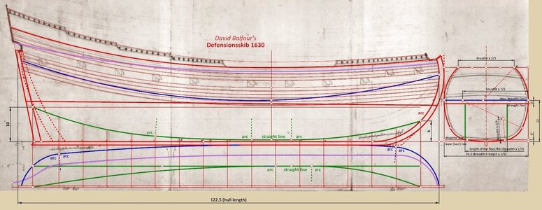
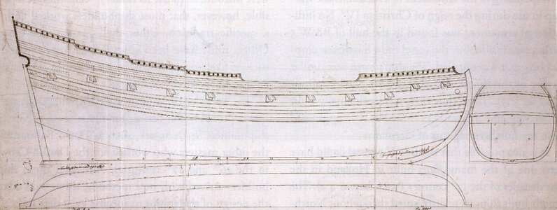
Plan of defensionsskib prepared in 1630 by Scottish shipwright David Balfour (Danish archives)


Anyway, this is primarily a kind of experiment, mainly for my purposes even before the 'attack' on Witsen's pinas, for further investigating the feasibility on a concrete example of a method I invented for rendering the shape of Dutch ships built by the bottom-first method, through the application of formal geometry. It is important to point out that this method is not abstract, but is grounded in the procedures known from the sources for the construction of the actual ships and the convincing construction plans of the period, mainly from the Danish and Swedish archives. It may be seen as a kind of continuation and development of the content of the previous threads on the bottom-first method, concerning the Rålamb's boyer and fluit (1691).

In English, probably the most information on Danish 17th-century defensionsskibe can be found in the work by Martin Bellamy, Christian IV and his Navy, and from book publications in Danish one should point out at least Danmark-Norges handelsflåde 1650–1700 by Jørgen Barfod, Christian 4.s flåde by Niels Probst and Dansk søfarts historie, vol. 2, 1588–1720 by Ole Den and Erik Gøbel.
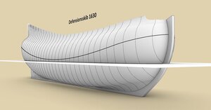
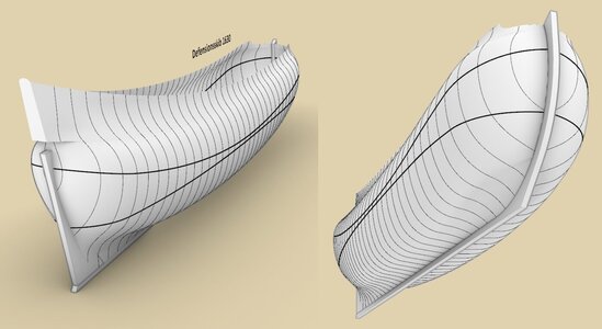
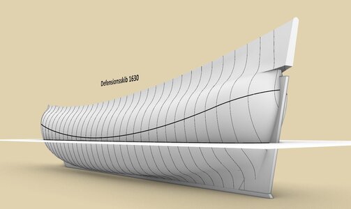
ViewCapture20230813_191307.jpg


Untitled-1.jpg


ViewCapture20230813_192553.jpg

.​
 
Last edited:
.​

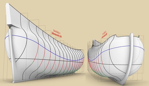
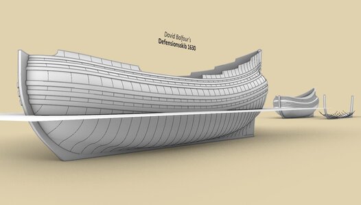
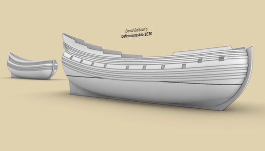
Essentially, the Balfour's plan depicts a fluit with modified shapes for better sea qualities, particularly weatherliness and speed, at the expense of a reduced payload for a ship of the same size. He seems to seek to achieve this aim mainly by making the bow sharper by raising the line of the floor (green) at this spot, and also by applying a rounder contour of the midship frame compared to the boxy variants of 'typical' traders.

In rendering the fluit shapes graphically on the plan, Balfour used the simplest geometric forms, that is, only straight lines and circular arcs. In fact, he used them exclusively in his other projects as well, however, in this particular case at least other geometric profiles were hardly needed.

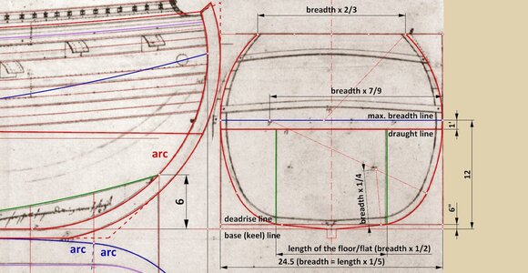
Curiously, the contour of the midship frame was drawn in a manner appropriate to the continental bottom-first method, which most probably means that the design was at the start intended for shipwrights using this very method. Firstly, he did not apply the lower breadth sweep, so characteristic of the Mediterranean and English methods, and secondly, the order of drawing floor/bilge sweep and hollowing curve/'flat' is appropriate for the bottom-first method, not the Mediterranean and English methods. More specifically, the 'flat' was drawn first and only then the bilge sweep tangentially to the 'flat' (and futtock sweep). In the Mediterranean/English method, it would be the other way around – the floor sweep would be drawn tangentially to the deadrise line first, and only then followed by the hollowing curve tangentially to the floor sweep.

Despite these efforts, a shipwright intending to build ship using the bottom-first method would still need to modify this design somewhat, particularly in the aft section, including by increasing the width of the sternpost at the bottom for more secure attachment of the first planking boards (garboard strakes). These expected modifications are suggested in the diagram below by the dashed lines.

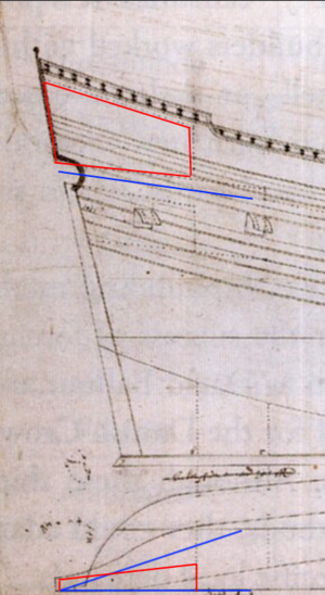
Due to the shape of the stempost, and unlike in Rålamb's fluit, the line of the breadth (blue) cannot be parallel to the wales, therefore its run in the sheer view had to be reconstructed.


ViewCapture20230814_214923.jpg


ViewCapture20230814_215158.jpg

.​
 
Last edited:
.​

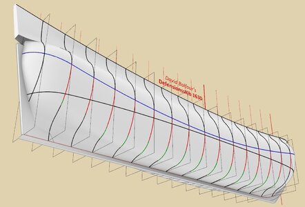
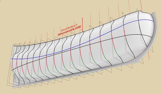
Here, the sweeps with the uniform radii have been colour coded. Bilge sweeps with identical curvature are coloured green, while futtock sweeps with the same curvature are coloured red. It can be seen that they are all applied along almost the entire length of the hull. Geometrically, the futtock sweeps (red) are tangent to the vertical lines at the height of the line of greatest breadth (blue), and the bilge sweeps connect in tangential way the 'flat' to the futtock sweeps. This is shown on the diagrams below.

Such a simple geometry is not only perfectly adequate to effectively shape the boxy hull, but may be even regarded as highly desirable. Or even more emphatically:

The uniform curvature of the vast majority of frame timbers is an important design feature with extremely momentous consequences, as it greatly simplifies the design concept and actual construction of a ship, as well as significantly reducing the cost and time of building the ship. Possibly this was the essence and most important feature of the invention of the boxy fluit.


ViewCapture20230815_160540.jpg


ViewCapture20230815_161656.jpg


Untitled-1.jpg

.​
 
Last edited:
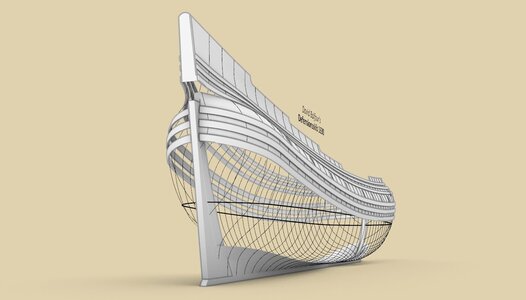
The last tier of the stern appears to be so narrow that it begs a question what the upper cabin (red) could be used for. The stern looks more like an airplane's vertical stabilizer. And even the position of the tiller (blue) makes it's operation relatively restricted.

1692167118553.png
 
Nice another experience of a shell first attempt. I will follow with interest.
I only see the same problem where I was fighting with. I did start to build the Hohenzollern model also with the bottom first. Only the plans and shape say something else. So I adept them to more shell first. When you look to Maarten's build it is a shell first ship. Flat and looks like a brick. Your plans and mine have on the bow the typical curve that "Maze"-build ships have. It was for me impossible to achieve that in bottom first.
20230816_084737.jpg
This S-curve in the bottom at the bow.
 
.​

@Martes

When it comes to the internal arrangement of the ship, it is probably best to refer to the excellent work by Niklas Eriksson, Urbanism Under Sail – An archeology of fluit ships in early modern everyday life (easily available on-line). In my opinion, this top room above the rudder tiller is primarily just a way to utilising the high stern so that this space is not wasted. The thing is, it was believed at the time that high sterns were beneficial because they helped steer the ship closer to the wind. Just as you associated it with the airplane's vertical stabilizer.

The maximum angle of tiller swing could have been quite sufficient, as for steering the ship the proper setting of the sails was largely responsible anyway. Somewhat simplistically, the sails were for making turns and the rudder more just for the correction of the sailing course.

.​
 
.​

@Martes

When it comes to the internal arrangement of the ship, it is probably best to refer to the excellent work by Niklas Eriksson, Urbanism Under Sail – An archeology of fluit ships in early modern everyday life (easily available on-line). In my opinion, this top room above the rudder tiller is primarily just a way to utilising the high stern so that this space is not wasted. The thing is, it was believed at the time that high sterns were beneficial because they helped steer the ship closer to the wind. Just as you associated it with the airplane's vertical stabilizer.

The maximum angle of tiller swing could have been quite sufficient, as for steering the ship the proper setting of the sails was largely responsible anyway. Somewhat simplistically, the sails were for making turns and the rudder more just for the correction of the sailing course.

.​
Sor ones there are a few builders, there has DONE their homework. excellent done. explication and resurce4 support, not as many newcomers ask SOS even before having done any research.
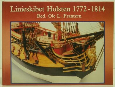
with your permission, I have copied the Images. although I do not fully understand the prints out Too old now 80. started more and less in the time where Calibot -Karl manche-in 1960 th. I am interested in the History here as Danish born and I have build the Norske LKowe two times. The 1th was before Laser-cut was on the marked- beginning in 1970. The 2Nd was the laser-cut Model in 1980 th. I have a ve4ry goog book of Holsten- another build from fabriksmester Krabbe

BRAVO AGAIN TO THOSE WHO DOES THEIR HOMEWORK FIRST

16-holsten 1.jpg
 
In my opinion, this top room above the rudder tiller is primarily just a way to utilising the high stern so that this space is not wasted. The thing is, it was believed at the time that high sterns were beneficial because they helped steer the ship closer to the wind. Just as you associated it with the airplane's vertical stabilizer.

I remember since we discussed it sometimes, and that's why I mentioned it. :)

After looking into the Eriksson book, it seems to me that Balfour has taken the narrow stern superstructire to somewhat of an extreme level, comparing both to the wrecks and the depictions, making the ships very curiously looking.

As to the tiller, I agree, it should have been probably sufficient. In merchant use the ship would hardly need more and as a warship the enlarged crew would be enough to ensure maneuvering with the sails.
 
.​
@Steef66


Hi Stephan,

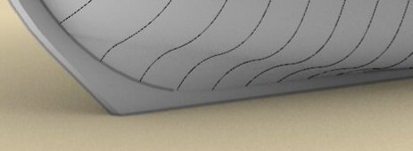
Your comments on this particular 'detail' are particularly important and interesting to me. As a matter of fact, I have prepared as many as three variants of the gripe: with a concave (shown here), a straight, and also a slightly convex cross sections. I think different shipwrights could have used all three forms at the time, while interpreting Balfour's plan, depending on their preferences and maybe also abilities. If you look closely, the smaller fluit at the back in my renders has just the slightly convex transverse gripe lines and consequently fuller bow lines, although indeed this is faintly visible in the attached graphics. Finally, while thinking on this very matter, I have come into conclusion, that if the shipwrights were able to shape the 'flat' at the stern in a concave way (transversely), they could have been expected to do the same at the bow.

Anyway, I will return to this intriguing matter in more detail later, as I am currently away from home and do not have access to the necessary sources and materials. For now, I'll just add that this is why your experiences in applying the bottom-first method in scale (I'm thinking now especially of you and Maarten), are so helpful and interesting.

.​
 
.​
@Steef66


Hi Stephan,

Your comments on this particular 'detail' are particularly important and interesting to me. As a matter of fact, I have prepared as many as three variants of the gripe: with a concave (shown here), a straight, and also a slightly convex cross sections. I think different shipwrights could have used all three forms at the time, while interpreting Balfour's plan, depending on their preferences and maybe also abilities. If you look closely, the smaller fluit at the back in my renders has just the slightly convex transverse gripe lines and consequently fuller bow lines, although indeed this is faintly visible in the attached graphics. Finally, while thinking on this very matter, I have come into conclusion, that if the shipwrights were able to shape the 'flat' at the stern in a concave way (transversely), they could have been expected to do the same at the bow.

Anyway, I will return to this intriguing matter in more detail later, as I am currently away from home and do not have access to the necessary sources and materials. For now, I'll just add that this is why your experiences in applying the bottom-first method in scale (I'm thinking now especially of you and Maarten), are so helpful and interesting.

.​
This point was for me on personal experience. My English isn't that good, but I understand you name that S-shape, Concave way. My experience about the concave way on the stem was that when I tried to get that shape in the planking of the bottom. The bow went to sharp, almost like an schooner (not that sharp, but to much for a Dutch ship). I tried to keep the bow like a brick, but I wasn't succeeded (reason was because once I start to go with the planking on the bowto go narrow for the concave shape, I couldn't go back wide). Maybe when I build the bow like Maarten did, I could manage this shape. But I let the planking of the bottom end on the stem post. So I went back to the drawing table and start again. Now I have the "brick"-shape in my bow like the typical Dutch bottom-first ships. No concave shape. Impossible to get that in it with this building method I use.

I'm curious about your insights about this, when you're at home.
 
.​
@El Capi

Hello Peter(?),

Many thanks for your comment. Perhaps it will please you to know that I am also intending to work out some other Danish ships from the early period if only time permits. For example the river frigate Stormarn 1703. In fact, there is so much extremely interesting material just in the Danish archives! A veritable horn of plenty! :)

.​
 
Last edited:
If you have the loft surfaces of your fluyt, you can, depending on the 3D toolset you're using, define all planks, including inserts and stealers, from the bottom up. This would allow you to check in advance whether or not the surfaces you defined results in a somewhat realistic planking arrangement.
If I interpreted your renderings correctly, there are quite some concave/convex and vice versa transitions.

That shape of the aft deck is befuddling, other than some sort of aerodynamics, as you pointed out, wouldn't make sense at all, given that volume was at a premium.
 
Last edited:
That shape of the aft deck is befuddling, other than some sort of aerodynamics, as you pointed out, wouldn't make sense at all, given that volume was at a premium.

Such small superstructures, aside from aerodynamic qualities, and lack of upper battery were reducing overall topweight, and thus increasing stability, which, probably, was very important for such an unusual length-to-beam ratio. As later large British East Indiamen, which were also long, boxy and narrow, those ships were probably relatively fast, weatherly, but difficult to handle and maneuver.

All this makes the design even more curious, and in some sense quite futuristic.
 
Last edited:
.
If you have the loft surfaces of your fluyt, you can, depending on the 3D toolset you're using, define all planks, including inserts and stealers, from the bottom up. This would allow you to check in advance whether or not the surfaces you defined results in a somewhat realistic planking arrangement.

This is as perfectly possible to simulate as you suggest, and has, incidentally, a close link to Stephan's comments, but this very attempt too has to wait a bit until I get home.


That shape of the aft deck is befuddling, other than some sort of aerodynamics, as you pointed out, wouldn't make sense at all, given that volume was at a premium.

Martes has elaborated above on this matter in such a good and compact way at the same time, that possibly hardly anything more needs to be added here. :)

.​
 
.​
@El Capi

Hello Peter(?),

Many thanks for your comment. Perhaps it will please you to know that I am also intending to work out some other Danish ships from the early period if only time permits. For example the river frigate Stormarn 1703. In fact, there is so much extremely interesting material just in the Danish archives! A veritable horn of plenty! :)

.​
You should try the Holsten. in the book about Holsten, there is a huge amount of its life. It was taken price with the British, changed name and served some here. I do not have the bool anymore -giving free to a builder, but I have scanned the whole book, so if needed I have the info and much more. happy building
el cape
 
.​
You should try the Holsten.

True, it's a great book and of course it's in my home library. The point, however, is that in the Holsten 1772 period the ship design is already, or should be better known. My activity, on the other hand, focuses on earlier, less well understood periods where there is still room for pioneering achievements or even discoveries.

.​
 
Last edited:
Such small superstructures, aside from aerodynamic qualities, and lack of upper battery were reducing overall topweight, and thus increasing stability, which, probably, was very important for such an unusual length-to-beam ratio. As later large British East Indiamen, which were also long, boxy and narrow, those ships were probably relatively fast, weatherly, but difficult to handle and maneuver.

All this makes the design even more curious, and in some sense quite futuristic.
Hello Martes,

Thanks for your explanation, it's appreciated.
Still, I have difficulty understanding the function of that piece of superstructure, especially when it's only aerodynamic. I would guess that the lateen sail could serve that function as well, against less weight on the wrong side of the center of gravity.
Having said that, I don't claim to be knowledgeable about this subject and yes, the design is indeed quite curious and futuristic.

Kind regards,

Johan
 
Still, I have difficulty understanding the function of that piece of superstructure, especially when it's only aerodynamic. I would guess that the lateen sail could serve that function as well, against less weight on the wrong side of the center of gravity.

It was quite a surprise for me, but it appears that was the belief at the time. The mizzen mast was usually positioned more forward than in 18th century or later, and part of the stabilizing function of the spanker sail was - again, apparently - delegated to the high stern superstructure. Apart from that, the structure could have been used for positioning musketeers as high as possible during boarding action.

Note, however, that Balfour does make the structure extremely and very unusually narrow, and most ships, even fluyts, had much wider sterns, so this configuration is in no way typical.
Until today I believed the narrow decks and superstructure of fluyts were designed to avoid payment of too much toll. This belief was shot to pieces, but I couldn't find another reasonable explanation.
Your remark of "the belief at that time" does actually make a lot of sense; we are looking at these 400 year old designs with our 21st century mindset and knowledge. Our views will be quite different from those of years long past. Still, very intriguing, since "form follows function", or maybe not?
 
Back
Top