Belaying Question

Joined
Sep 13, 2022
Messages
22
Points
28

I’m working on the Gerard Schmitt kit of the Prince de Neufchâtel (1/64 scale). I’m finally at the rigging stage and have noticed that according to the diagrams, there are numerous instances where at least two lines belay to the same pin. I’m new at this, so I feel like it’s a major accomplishment just to get one line properly belayed. There doesn’t appear to be enough room on the pin to property tie off a second line.

Is this just another example of practice, experience, and perseverance making it better? Am I using incorrect line or pins? Is the pin rail too thick? For all of the above I’m using what was supplied with the kit. Is there a specific method I should be using or anything else that I should be doing?

Taking advantage of the years of experience, expertise, and advice from the experts on this forum has been tremendous, I had no idea that all you guys were out here. Thanks again from a baby newby.
 
Take a look at this topic in which the same problem was discussed - there you can find also several drawings and photos


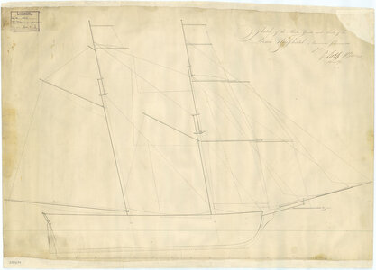
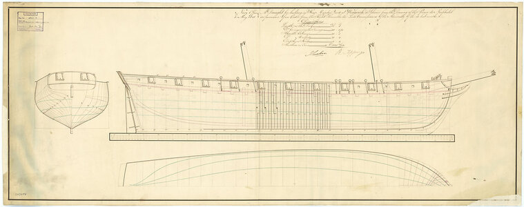
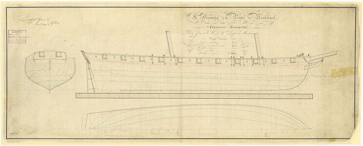
BTW: there are three contemporary drawings existing of the ship (made after her capture)- not really helping for the actual problem, but nice to know about them

Prince 3.jpg

Prince.jpg

prince2.jpg

 
I'm sure it probably occurred, but I would think not as a general rule.
It would be a mess of lines if they needed to modify the line belayed below the top one. They would have to remove the top line to haul on the lower line. It would really be a mess. But that is just my opinion and I have no documentation to back it up.

Also, I have never seen any documentation to note 2 lines (or more) belayed to the same point on any drawings of real ships. But then again, I've not made it my life ambition to examine all the belaying points on all the plans available. :D
 
Rigging belay points are not always an exact science…often each Captain had their own ideas as to where to belay lines. Having said that you can safely adjust a belay point without worry of doing something “wrong.” For example, simply belay the second line on the next pin in line. It would help to study the belay plan to determine if you are causing doubling at another point but the thought here is you can adjust belay points as needed and stay “correct.” Another idea is to add a new belay point such as a ring on the bulwark or on the deck near the pin rail, or if room remains add another pin on the pin rail. If you really want to be fancy you can add another small pin rail next to the one you are working with…suggest two or three pin rail. The idea is that solutions abound and it is ok to find a good alternative belay point! Besides, once finished, no one will ever go poking around to discover all the “mistakes” you made adjusting the belay points! And if by chance they do simply say “Captains choice!” :)
 
Last edited:
Thanks Jim for the encouragement. Being a natural follower of instructions, especially with something this unfamiliar and complicated, it’s extremely distressing to find out that kit manufacturers not only simplify things, but are often flat out wrong. Freeing myself from the ‘tyranny of the plans’ will make my new hobby much less stressful and much more enjoyable.
 
On my Carrack, there were not enough belaying pins on the forecastle to connect what I felt was needed, so rather than double-belay them (which I also think was not done much), I just added 4 new belaying pins, spacing them a bit closer. We'll see how it works out.
 
I work on current sailing vessels where double belaying is not exactly common but we do use it in some situations where there is limited room. The key is that the two lines cannot be in conflict with each other. As an example, on the reconstruction Kalmar Nyckel, the cat stopper and the fore course bowline are belayed on the same cleat. One never needs both lines under tension at the same time, so a double belay works.

Fred
Thanks Fred! I have learned something new today!
 
“Ha… I laugh in your general direction as I one-up you!”
image001.jpeg

My current build, OcCre’s Candelaria, has multiple doubles and three triples on the bow! Since there are many pins mid & aft that are not being used, I plan on making that 11-pin rack maybe 15 or 17, and maybe also add small racks port & starboard.

image001.jpeg
 
“Ha… I laugh in your general direction as I one-up you!”
View attachment 400900

My current build, OcCre’s Candelaria, has multiple doubles and three triples on the bow! Since there are many pins mid & aft that are not being used, I plan on making that 11-pin rack maybe 15 or 17, and maybe also add small racks port & starboard.

View attachment 400904
LOL. My favorite movie! . I know, it says a lot about me.:p
 
“Ha… I laugh in your general direction as I one-up you!”
View attachment 400900

My current build, OcCre’s Candelaria, has multiple doubles and three triples on the bow! Since there are many pins mid & aft that are not being used, I plan on making that 11-pin rack maybe 15 or 17, and maybe also add small racks port & starboard.

View attachment 400904
Yeah, two lines belayed on the same pin should be avoided, but three is unacceptable. Add more pins if you can.
 
I had much head scratching on Occre Endeavour on this exact question and in the end after much procrastinating either doubled up on some pins while on others I moved some lines to the nearest unused pin of which there were not many. I had limited opportunity to add additional pins certainly by the time this issue became obvious. If I had realised the issue earlier in the build further modification might have been possible.
 
I had much head scratching on Occre Endeavour on this exact question and in the end after much procrastinating either doubled up on some pins while on others I moved some lines to the nearest unused pin of which there were not many. I had limited opportunity to add additional pins certainly by the time this issue became obvious. If I had realised the issue earlier in the build further modification might have been possible.

I get where you’re coming from. Luckily I had a scale model on the bench when I bought my kit, so I had the time to really scour the instructions/prints during my lunches at work before starting the build. As a newb to wood ships, I really do like OcCre’s layout of their instructions, but I found a number of blatant errors and things just that just left me going “huh?”.
 
I get where you’re coming from. Luckily I had a scale model on the bench when I bought my kit, so I had the time to really scour the instructions/prints during my lunches at work before starting the build. As a newb to wood ships, I really do like OcCre’s layout of their instructions, but I found a number of blatant errors and things just that just left me going “huh?”.
Hull construction instructions were generally very good but rigging instructions definitely need improvement … don’t think Occre have tried to build the ship from their own instructions. I used many different highlighter pens to help mark up the rigging plans which definitely helped. What would be useful is a cross reference table of the mast/rigging plans and the deck plans showing where ropes would be attached. That would then show up gaps in the plans.
 
In doing my research of my build of AL's L'Hermione I have seen on YT videos of the replica ship many instances where cleats have been attached to the shrouds with rope and used for the running rigging. Maybe an easy and historically accurate solution? Adding cleats to the lower masts?
 
Doubling up on belaying pins.
I don't know if this extract from one of my posts in the REvenge build log will be of any use.
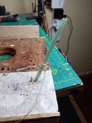
)If the line terminates at a pin that is already in place then the method illustrated below can be used. The line is tied round a drinking straw using either a clove hitch or single overhand knot. The straw is placed over the top of the pin and the knot pushed down to the top of the pin rack. I use a wire loop for this. The knot is held down while the straw is removed then pulled tight or tweaked to adjust the tension.
On the OcCre model there are many cases where several lines end on the same pin. I'm not sure that this is realistic but option 3 helps to achieve it.
I have illustrated this by implementing it on the bench rather than on the model. There is one pin inside the straw.
A 'decorative' coil can be tied independently and added to the pin to hide the above bodges.
belaying.jpg
 
Back
Top