1930 Bentley Blower by Aifix 1/12 build log

Still quite busy at other things but managed to try out the new resin printer I got for my birthday. I still need to make some type of enclosure with an exhaust fan, the resin has a powerful smell and I really don't want to be breathing those fumes.

Here's a picture of my firts prints.

From left to right, first pair not too bad, second pair printed good but I forgot to ajust the scaling and last pair is a nice print.
20231206_215404.jpg

The real part
20231206_215336.jpg
 
Hello everyone, I took a break from the Bentley these past few weeks in order to concentrate on my new resin printer. This thing is really hard to dial in but I'm slowly getting the hang of it, and I do mean slowly! My first try at the begining of december was promissing but dince then, the results were ok at best. Today, I finally printed a few parts that are worthy of being used on the bentley.

The horns have been glued to the kit's head light bracket

20231216_211331.jpg.960b8af01e42dcdd62c553aca2f5ea7a.jpg


And the throttle spring plate (thats the triangular plate between the carbs) has also been glue to the blower. The carbs aren't quite ready yet. It's kinda hard to see but they are 2 small lever mounted on the aluminium rod that will eventualy connect to tge triangular plate via 2 extension springs. And they should (maybe) be actuated by depressing the gas pedal.

20231216_211118.jpg.12f461a997ac9d23b79b1706a7bee44f.jpg
 
I installed the horn/ head light bracket combo today, farly satisfied with the result.

Here's what I was aiming for
20231130_201430.jpg
And here's the 3d model
20231130_201422.jpg
And here's the result so far
20231218_135607.jpg
20231218_155821.jpg

I also assembled the carburators (all 3d printed on my new resin printer) and installed them on the blower which is now connected to the engine. I just need to make the 2 brass fuel lines that go from the carbs to the fuel hoses and to add a oil feed line to the front of the blower and it will be complete. Next on the list will be to model and print proper looking lever shocks.

Here are some pictures of the carbs and blower.
20231218_151815.jpg
20231218_162145.jpg
20231218_162126.jpg
20231218_162135.jpg
The real thing
Blower Continuation Series - 7 - Supercharger.jpg
20231218_172332.jpg
20231218_164723.jpg
The real thing
Screenshot_20231218_220930_Photos.jpg
 
I installed the horn/ head light bracket combo today, farly satisfied with the result.

Here's what I was aiming for
View attachment 414943
And here's the 3d model
View attachment 414945
And here's the result so far
View attachment 414952
View attachment 414942

I also assembled the carburators (all 3d printed on my new resin printer) and installed them on the blower which is now connected to the engine. I just need to make the 2 brass fuel lines that go from the carbs to the fuel hoses and to add a oil feed line to the front of the blower and it will be complete. Next on the list will be to model and print proper looking lever shocks.

Here are some pictures of the carbs and blower.
View attachment 414946
View attachment 414951
View attachment 414949
View attachment 414948
The real thing
View attachment 414953
View attachment 414950
View attachment 414944
The real thing
View attachment 414955
Nice to see your progress, François. And the comparison between the real, the 3D and your model.
Regards, Peter
 
The shock absorber being done, my next task will be to run some micro gage wires from the head lights and gearmotor/starter all the way to the back of the car and eventually out of the still to be determined showcase and into a, also to be determined, electrical cabinet where there will be batteries and switchs to activate the head lights and the engine.
 
The shock absorber being done, my next task will be to run some micro gage wires from the head lights and gearmotor/starter all the way to the back of the car and eventually out of the still to be determined showcase and into a, also to be determined, electrical cabinet where there will be batteries and switchs to activate the head lights and the engine.
I hate to make you go back and change things, but your frame is the wrong color.... :D
 
Merry Christmas and happy new year to you, Francois.
Thank you for your posts and the pleasure you give.
 
Francois, I'm still waiting on when you will be filling the gas tank and starting that engine. I'm having a difficult time believing that this isn't an actual Bentley with your fabulous attention to detail
 
I wired the head lights today and they work. Just need to chrome them up. I also 3d modeled the grill rim as the one furnished in the kit is not really nice. I know that many modelers will cut away the center portion of the grill and add a real mesh. And I might end up doing just that but I'll try printing some more accurate rims first.

I have a proper size wire mesh that has a .04" aperture that gives me about 20 squares which is about right and a .005" wire that scaled up is 1/16", also correct.

Wired head lights
20231227_161124.jpg
20231227_161100.jpg

Test fitted on car
20231227_210309.jpg
20231227_210252.jpg
Lights on
20231227_211159.jpg
3d modeled grill rims
20231227_215748.jpg
Real thing
Screenshot_20231227_220921_Photos.jpg
Proper sized mesh
20231227_215821.jpg
Kit's head light grill
20231227_222245.jpg
20231227_222314.jpg
 
For those of you who are unfamiliar with the 3d resin printing process like I was, I thought it could be interesting to show the different steps requiered to print a part .

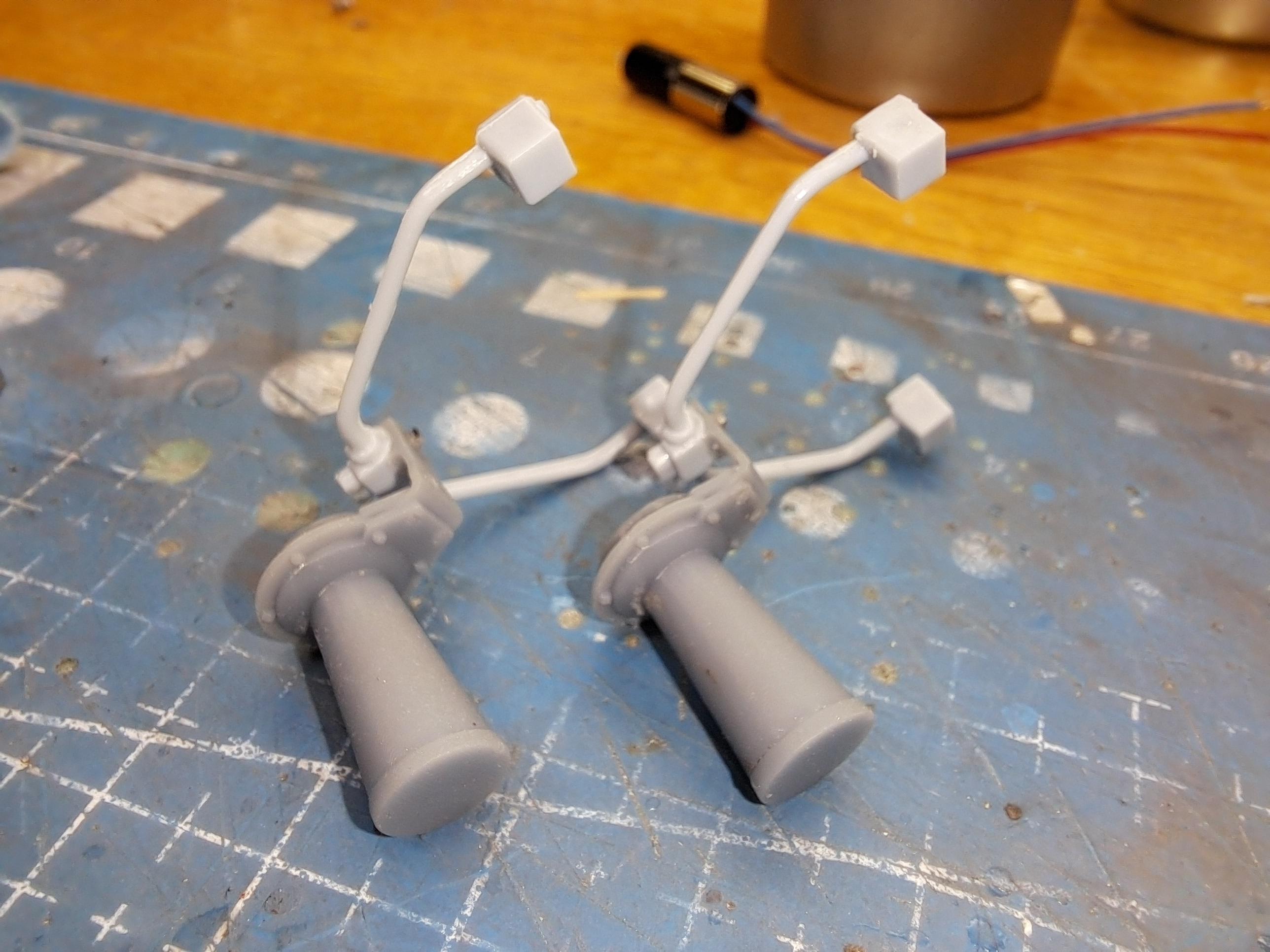
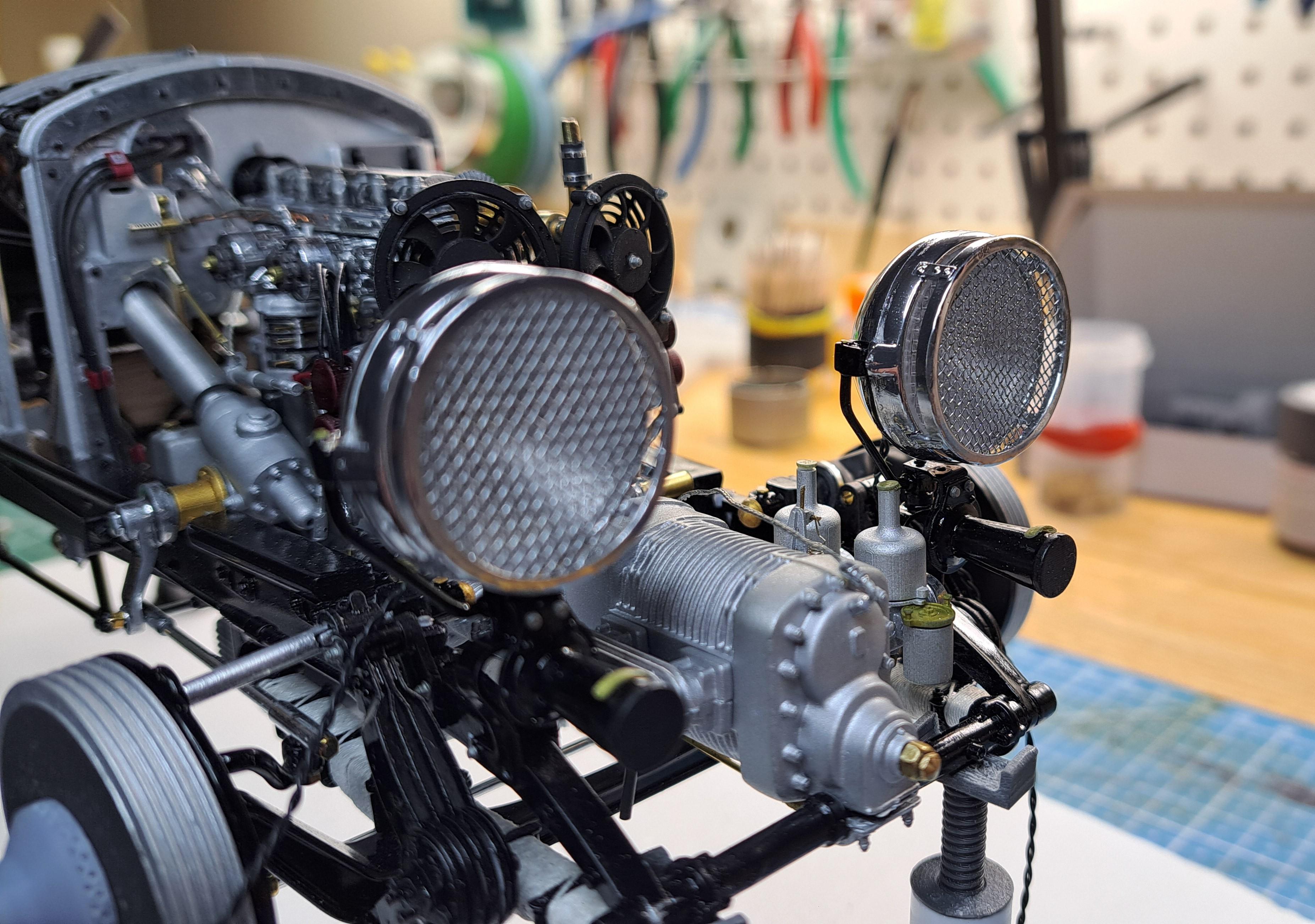
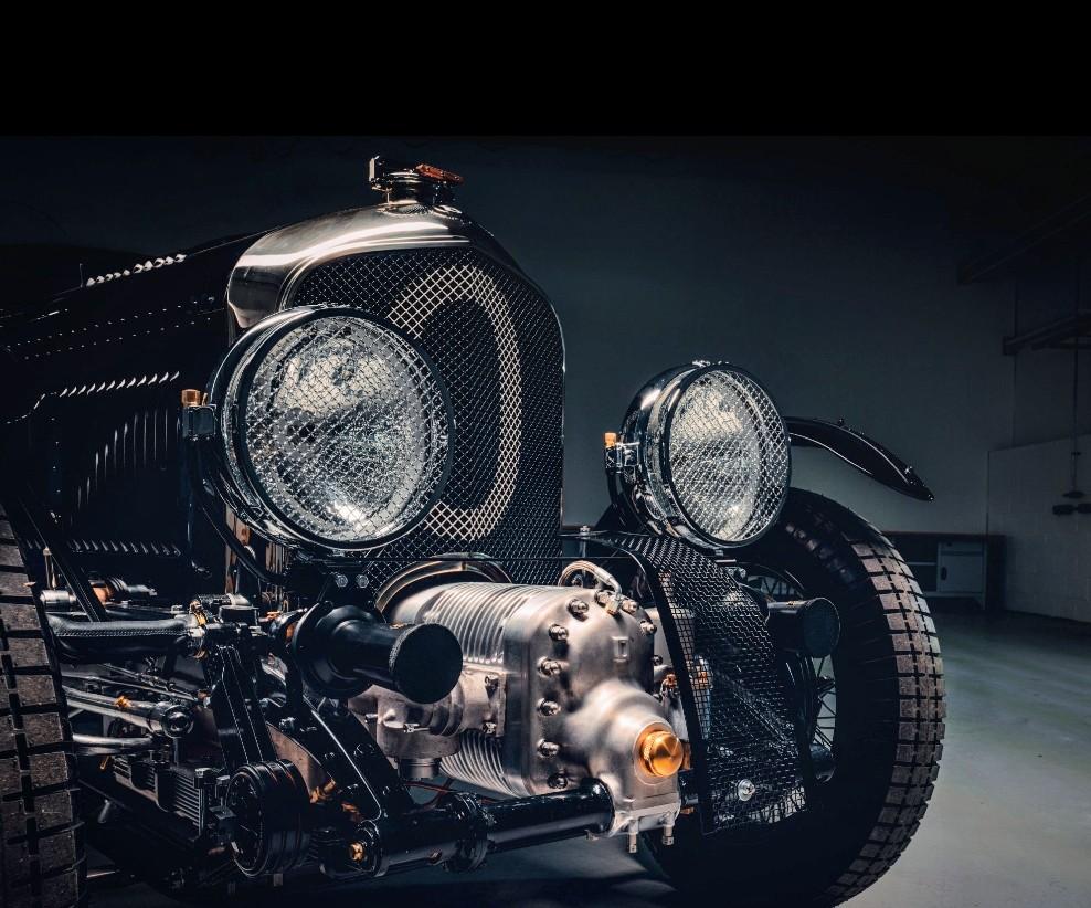
1- decide what to print. In this exemple, I wanted to improve the head light protection grill from this
20231227_222245.jpg

To this
Screenshot_20231227_220921_Photos.jpg

2- 3d model the part
20231229_071438.jpg

3- load the model in a slicer application. A slicer will literally slice the part in a multitude of layers. The number of layers depent on 2 things, the height of each layer, in this case it's 50 microns (.05mm) and the total height of the print. The taller the print, the more layers will be requiered and the longer the print will take. That's what fun with this process, the printing time is not dictated by the surface area being printed so a single small part of say 3mm height and 10mm square area will take as much time as 'X' of the same part as long as they fit on the printing plate. Now, this is where the game is won or lost. You have to give the proper orientation to the part so as to not have too much surface area being printed on each layer while taking care of the esthetics. You want to avoid supporting the part on visible surfaces because the anchor point will show a bit (or alot depending on their size and number). In this case, I wasn't able to avoid this but fixed the problem later on. Once oriented, you then add supports. The idea is to support the part at strategic point as it's being printed, avoiding overhangs.
20231229_071327.jpg
View attachment 20231229_071358.mp4

4- load in printer and print
20231229_034327.jpg
20231229_034514.jpg
5- wash part in washing station. I use a water wash resin so cleaning is done with water. Most resin will requier cleaning with alcool
20231229_043644.jpg

6- remove part from support structure by diping in boulingrin water for 2 to 3 seconds. This is not always necessary but will make separation alot easier.

Before boiling
20231229_042821.jpg
After 2 sec dip
20231229_043119.jpg

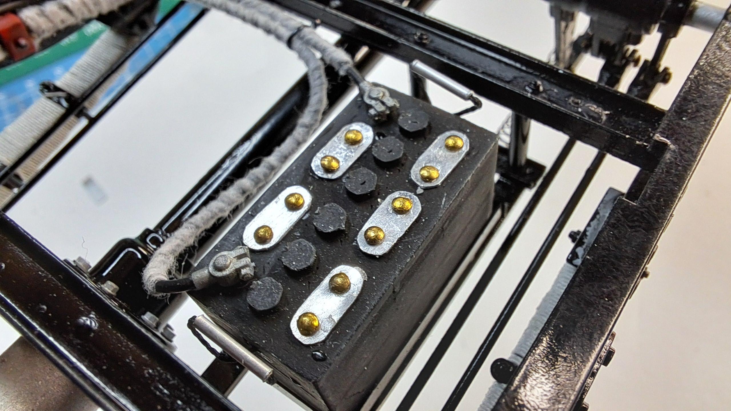
7- Cure in curing station. Most small parts will cure in 2 minutes. The longest I cured à part was 5 minutes. (The washing and curing uses the same machine, at least mine does)
20231229_043728.jpg

After curing ( notice the bumpy top surface)
20231229_044048.jpg

8- part finishing. Here you have to remove any anchor points that will be visible with either a blade, snippers or sand paper. I this case, not being able to support the part on a non visible surface ( I tried 5 different orientations but only one worked, I'm sure that someone with more experience could have achieved this), I printed a sanding tool since this part is very fragile.

Sanding tool
20231229_061002.jpg

And after sanding
20231229_061401.jpg

All that is left to do is to install the wire mesh
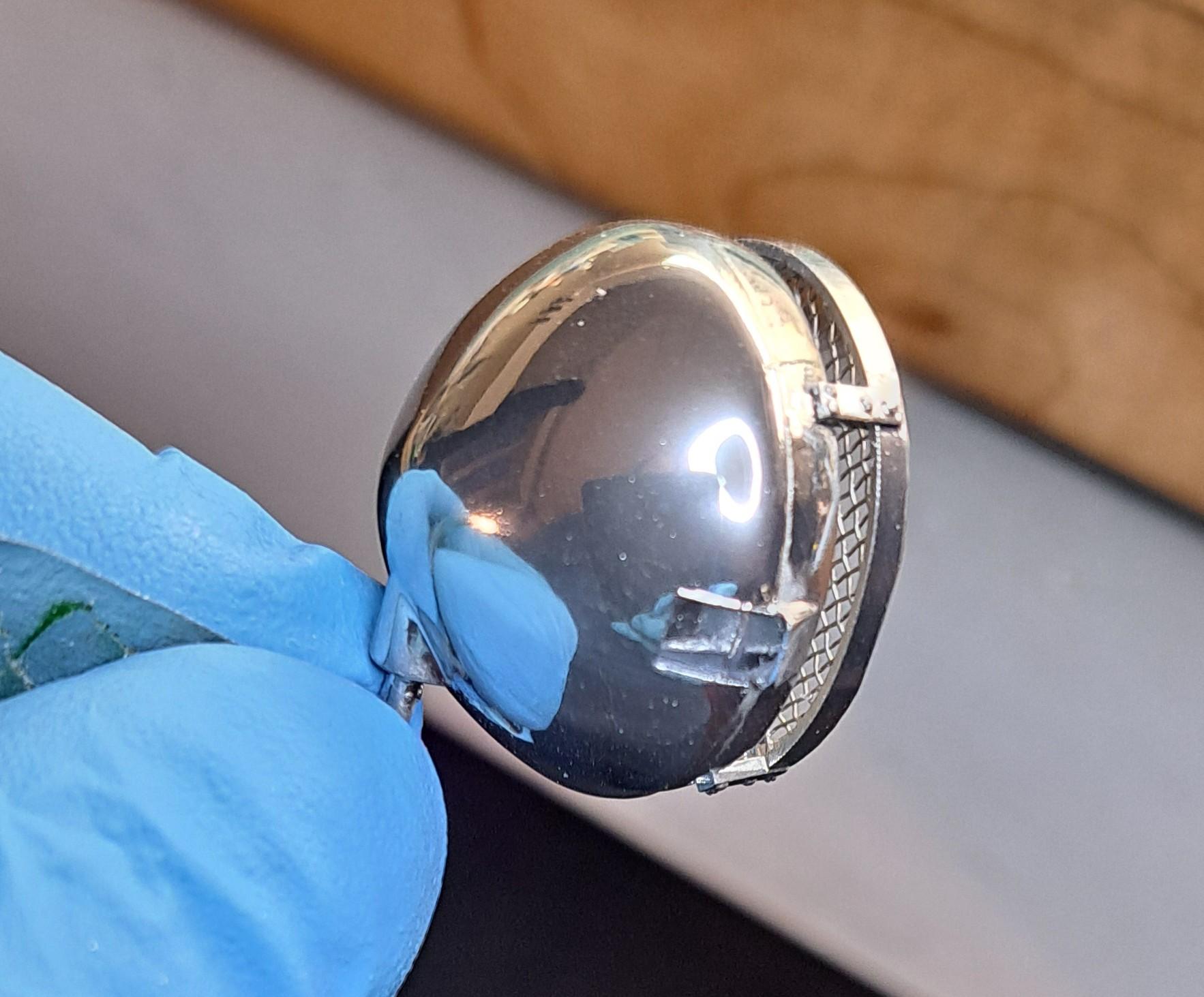
20231229_082226.jpg

and chrome.
20231229_083205.jpg

So that's it, hope you enjoyed this!!
 
Great review of 3D printing. What I don't understand is what the process to design the item though I "assume" that you start with a cad or similar drawing of some sort and feed it in the printer to duplicate in resin at some chosen scale
 
Dave,
I'm lucky, 3d modeling and part design was my job so I pretty much design whatever I want on a cad software. Others that aren't as lucky as me have to find someone to 3d model for them.
Wow, ain't that a coïncidence!!
Just so happens I offer that service!!
 
Dave,
I'm lucky, 3d modeling and part design was my job so I pretty much design whatever I want on a cad software. Others that aren't as lucky as me have to find someone to 3d model for them.
Wow, ain't that a coïncidence!!
Just so happens I offer that service!!
I "guessed" correctly then about how the process begins! Not that I'm going to buy/use a 3D printer but ya never know where things may lead. Thanks for the confirmation - and I'll keep your last comment handy, just in case:D
 
I had a moderate set back with the gearmotor that is supposed to run the drive train. While connecting the wires to the motor, the leads broke from the motor, too close to the end plate to be repaireble.

20231230_103249.jpg.e5a6b5a3d481f701dc97116abc999496.jpg


Fortunately, when I ordered the gearmotor, I ordered 2. One high ratio ( the one that broke) and one slightly lower ratio. So I very carefully removed the rear housing covering the back end of the motor and the spur gear and was then able to remove the broken gearmotor. I then redid the terminals in a more sturdy way on the new motor.

20231230_103304.jpg.30cfb1f74a25f0c02c02643ba7da61fa.jpg


I had to reprint a new rear housing and spur gear and after a few hours of coaxing, was able to refit the new motor and complet the wiring.


View attachment 20231230_163606.mp4

I also wired the faux battery, complete with proper battery terminals

20231230_163441.jpg.3ac2b7b3559adac333a1672058b94061.jpg


I then set out to assemble and dry fit the newly chromed head lights. Very very happy with the result !!


20231230_164120.jpg.999c68a11fb64e2b225bd3b99f0d4111.jpg


Screenshot_20231230_201009_Photos.jpg.63685969687914023882be5fbdf951aa.jpg
 
Back
Top