1:20 Scale Victory & Constitution Gun Models by Signet [COMPLETED BUILD]

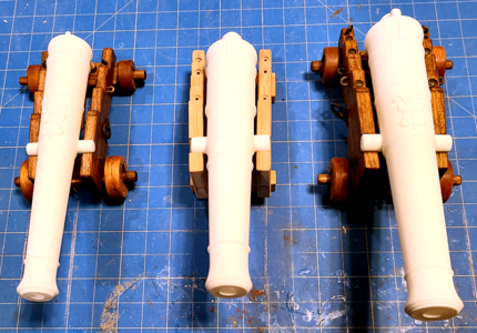
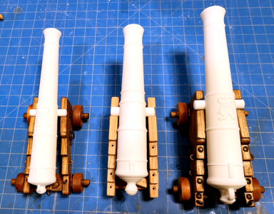
Oh Happy Day! My 3D-printed barrels came today! I've placed them on the two HMS Victory carriages for viewing, and put some of the pieces for the USS Constitution 24-pounder carriage for its barrel, without quoins on any of them or even bed on the Constitution gun. The white material doesn't photograph the detail well at all, but you get the idea:
1670295646206.png
1670295660220.png

I'm very happy with the barrels. I ordered them from i.materialise.com, which is located in Belgium, but use 3D printers located around the world. These came from a location in Washington state, USA. They were ordered in Polyamide, using SLS (Selective Laser Sintering), a printing system that places an extremely thin layer of heated powdered material for each layer, and uses a laser to melt the layers/pieces together. While an industrial process often used for prototypes and moving parts, it has less detail than resin printing, yet was much less expensive. I assumed, from what I'd read, that while detail wouldn't be as good as resin, the texture should work out well for simulating cast iron barrels in this scale, and it turned out I was right. Blind squirrel, nut, yeah.

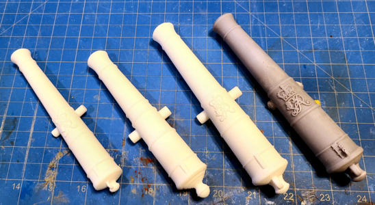
Here's a shot of the 3 barrels with the resin one my son made for me some time ago:
1670296110080.png
I feel the detail of the crest is plenty good enough, maybe rounded just enough to be more realistic. Knowing/suspecting the limitations of SLS as far as detail goes, I removed the Gunlocks from the barrels, as I felt they would not be reproduced well enough in SLS. I may get my son to print them separately for me (once he's situated in his new home) and add them later. Oh, BTW, SLS requires no supports, so there is no scarring that might require sanding, changing the texture of them.

Anyhow, I love them, think the detail on them is perfect, and the trunnions measure within a couple thousandths of the specified size (slightly oversize). They will no doubt be painted black, but I'd like to see some kind of wash on them so we'll have to see on that.
 
The barrels are looking very good - well done
 
I put a coat of satin black spray paint on one of my ruined barrels, and didn't like it. Going to get some flat black or something else and try.

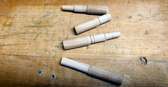
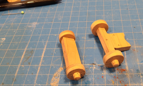
In the meantime, I needed new "axles" I'll call them, the extensions for the axtrees I've made above that were originally a part of the axtrees in carriage construction. They're fairly simple turned pieces of wood, to be inserted into the already made pieces, to form the complete axtrees. But being an engineer, I thought I'd greatly complicate this situation and show step-by-step how I made these pieces. I have no lathe, and lacking one had to resort to cobbled-together methods to produce something that looked okay and worked well. This - is that story (tongue-in-cheek laugh):

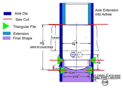
Using the drawings I posted links for in post #34 of this topic, and after several failed ways of making them, I came up with the following diagram of the ends of the axtrees, which I shall call axles, drawn over top of the detail of the ends of the axtrees:

1670378628166.png
Messy though it is, this drawing shows the steps to produce the axles, with further pictures during the process below:

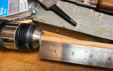
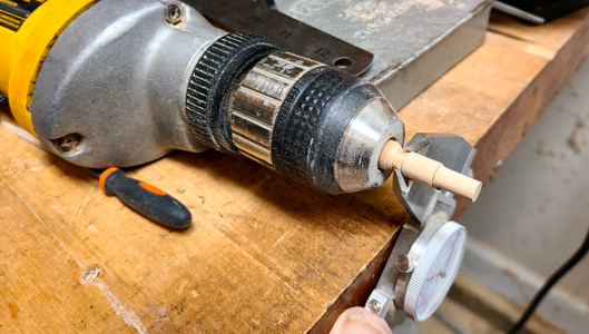
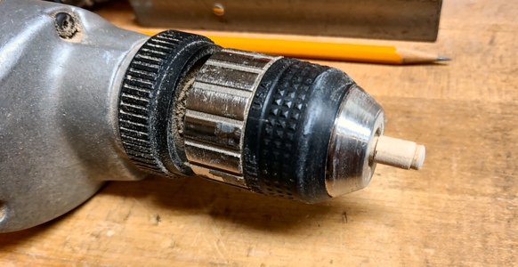
I wanted to stick with all cherry wood for my carriages, and without a lathe, it was easier to start with cherry dowels. I used a 3/8" diameter for the axles in this case. I chucked the dowel into my 3/8" capacity electric drill, and measured off a good 1" from the end to provide slightly over that length of turned diameter:
1670379024559.png
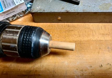
After cutting to length and inserting for work:
1670379109744.png
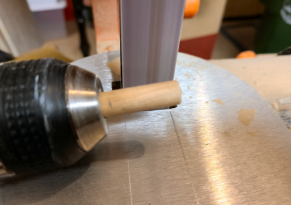
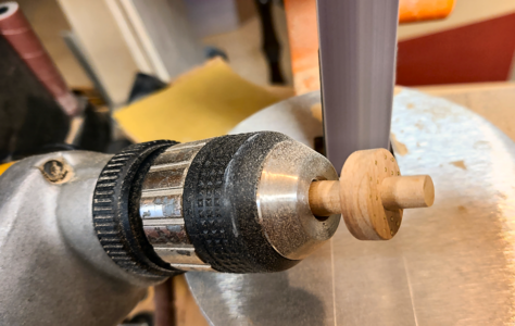
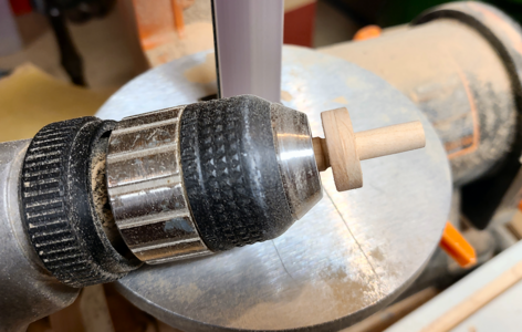
I then used my "patented" method to "turn" the dowel to the correct diameter: Held in the electric drill, rotating normal/clockwise and run at fairly high speed, I lightly bring the dowel against the belt of a 1" wide belt sander:
1670379250843.png
The object is to sand down the 3/8" rod to about 5/16" (the original 6 1/4" diameter divided by 20 or 0.3125"), or a slip fit for the truck/wheel over it's mating axle. This can be sanded down very quickly, so a light touch helps and keeps it concentric as well. I also remove more material at the end, so I can begin sliding the truck over the axle:
1670379468850.png
Continuing with the process:
1670379524897.png
Continue sizing the 5/16" area to the truck until it is a close but loose fit toward the end nearest the drill (which will be the outside of the axtree):
1670379637510.png
It doesn't matter if the end of the dowel is a bit undersize, as it will be turned smaller later, but you want a good fit at this location and toward the center of the 1"+ area. This is shown by the dark blue area removed on the drawing at the top of this post.

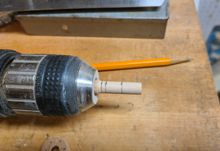
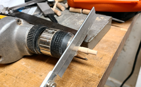
I then measure in from the end about 0.5", to allow for the extension of the axle that will insert into the 1/4" holes in the axtree centers plus extra, then 0.49" for the 9 3/4" length of the axle extended out from the rectangular portion, and back 0.11" for the reduced diameter area:
1670379853182.png
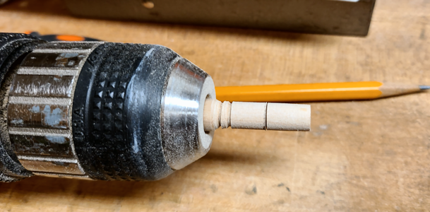
I then used a fine-toothed, thin saw blade to cut grooves at the lines while the drill ran, 1/32" +/- deep as shown as red cuts in the first diagram above:
1670380493089.png
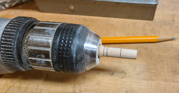
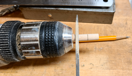
Next I used an equilateral triangular file to make grooves as shown in red in the diagram above:
1670380633599.png
This is in only 2 of the grooves. The purpose is that while the saw cuts specify the exact location of a diameter transition, the grooves begin to shape dowel to the proper contour:
1670380755562.png
As required, I deepen the groove closest to the drill, but not enough to weaken it. Likewise, the groove at the other end can be deeper, because it will not be visible once the truck is in place. The center groove shouldn't be too deep, though, as it will be visible.

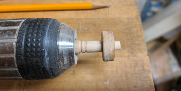
Back to the patented drill-versus-belt-sander routine to reduce the size of the outer portion (teal in the first diagram) to 1/4" in my case, as that is the size holes I drilled into the center portion of the axtrees. I'm using a scrap wheel made previously with a 1/4" drill determine the proper fit:
1670380995651.png
It also fits the center of the axtree, but is too long at this point (but we want that as you'll see later):
1670381115690.png
I then used the triangular file to turn down the diameter between the 2 closer marks to 0.268", but only on the inside of the V-groove closest to the center. The 0.268" comes from the drawing diameter of this area over the iron pipe reinforcement of of 5.56", divided by 20 for scale and subtracting 0.010" for the thickness of the tape that I will be using to simulate the iron pipe:
1670381187222.png
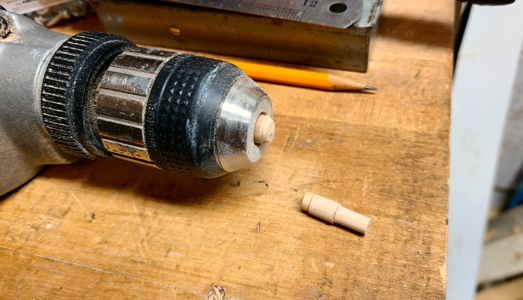
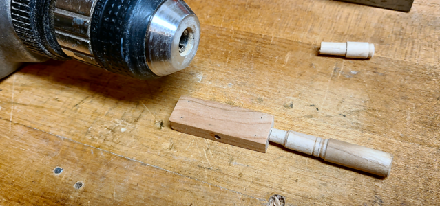
Next use the saw blade to deepen the inner cut to cut the axle off of the dowel:
1670381438521.png
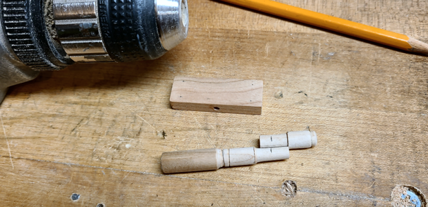
The roughed-out axle, after finding it amongst the trash, scraps and sawdust on the floor, where Murphy's Law requires it to fall:
1670381570936.png
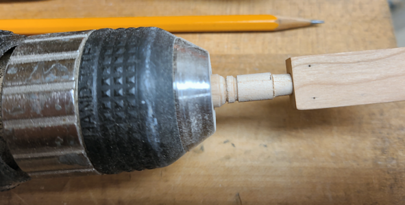
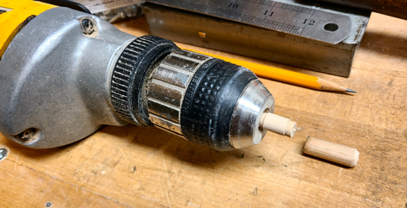
Now chuck the axle in the drill using the smaller end, in order to finish the profile:
1670381643236.png
The V-grooves are rounded and the end radiused as per the drawing to best simulate the axle (removing the purple portion in the above diagram).
1670381725185.png
Using one of my mistakes, I mark how far into the center of the axtree the axle will go. These holes were all drilled using brad point bits, which provide a flat, smooth hole bottom, with a centered deeper portion:
1670381845377.png
Then mark the proper length of the extension on the axle:
1670381915070.png
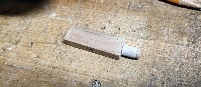
And cut to length, rounding any burrs. Insert into the center portion, and do it 3 more times for each carriage:
1670381987584.png
I mentioned mistakes; my patented method is very quick and can yield great results, but is susceptible to over-sanding, which can occur during any of the steps:
1670382115051.png
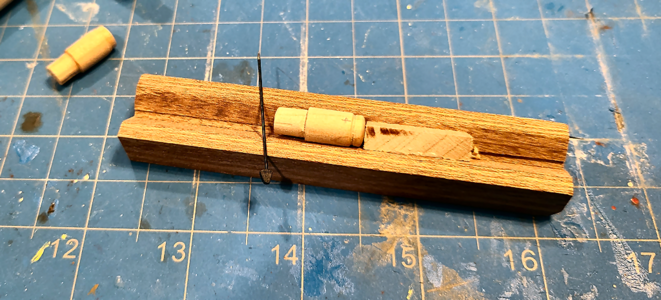
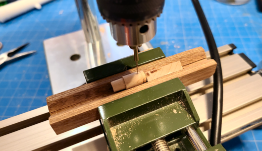
My previously made and used makeshift jig to drill centered and properly located holes for the linchpins (one shown, made of a ball-end needle) worked well again for drilling:
1670382301956.png
I wanted a consistent distance from the end of the axtree to the hole center so as to expose a consistent amount of the shaft. The jig and small drill press made this a snap:
1670382424507.png
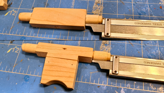
I used a dial caliper to accommodate variations in length of the extended axle portion, so they would appear the same after truck mounting. I inserted a pin in the retainer holes to align them properly when gluing. I just used a small amount of Titebond glue on the INSIDE of the hole so that no glue would be forced outside and stain the assembly:
1670382720186.png
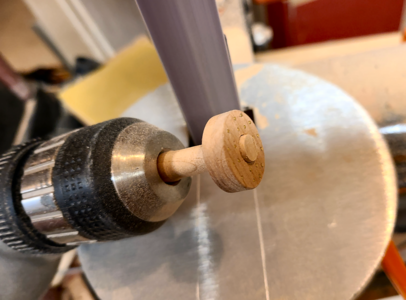
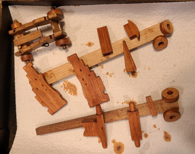
The final axtrees with trucks in place, ready for staining and further assembly:

Whoops - I've reached my 25-file limit for pictures! Time flies when you're having fun. I'll post the final pic in the next post.
 
Last edited:
The final axtrees with trucks in place, ready for staining and further assembly:
1670383003875.png
The type of pin I used for linchpins is shown at the upper left. A bit bent from precisely locating the shafts as the glue was drying to be in the right location.

I apologize for my over-wordy, and in particular over-pictured, description of my method for this relatively simple part and process. But I wanted to document it, and figured what the heck, it's my thread, and just went with it. Hopefully that will help some people making similar parts without a lathe. I'm sure it's all obvious to most builders on this site, but if it keeps others from wasting their cherry dowels (at $5.99 a pop), it will be worth it. To me. Your mileage may vary. :)
 
Last edited:
a wonderful result
I the last photo we can also see very well, that the single wheel was built by two halfs of the thickness - Bravo!
 
a wonderful result
I the last photo we can also see very well, that the single wheel was built by two halfs of the thickness - Bravo!
Thanks for noticing. Actually, they should have been made in 4 pieces, per the drawings, with each side being split as well. No doubt so that 18" wide stock would not have to be used. But I didn't see that until I was done, and had no more thinner material to make them out of. I made some thin saw cuts to represent it, but they aren't that noticeable. Plus the grain of the same piece of wood gives it away anyhow.
 
I'm trying to decide what color to paint the barrels. I've taken the resin barrels my son made for me, and painted one flat black, and the other what is supposed to be satin black. I think it looks a bit glossy for satin black, but shook it carefully. The flat black is Rust-Olium Ultra 2X Flat Black, while the satin is Rust-Oleum Universal Satin Paint & Primer in One:
1670539289098.png
1670539471744.png
Both of these barrels were made by my son with resin, and I consider them decent (although the new barrels I got used a different process). One has a failed end, and the other I ruined when trying to turn down the trunnions. The satin finish seems to show up more irregularities (that I couldn't even see) more than the flat. I was going to try using a "Hammered" finish paint, but could only find that in gloss, and knew I didn't want that. I'm sure in real life these are sprayed a fairly glossy black, but models usually benefit from less gloss.

Anyhow, I was wondering what you forum readers thought was best?
 
I'm no expert so I'll ask a question: why do you think gun barrels were sprayed with anything? Wouldn't they have been left in their natural (cast or otherwise) condition?
I doubt very much that they would be left as cast/machined. Iron rusts, and sea water would only accentuate that. I'm sure they weren't "sprayed", but would have been coated by brush. That and every iron gun currently onboard ships today are painted to my knowledge.

Bronze guns probably weren't painted, but I can't imagine not painting cast iron. Of course, this is just my logic on the matter, and current examples.

I also found a thread here on shipsofscale.com about this.
 
Continuing with the wood pieces of the Constitution's 24-pounder carriage, they have now been given 2-3 coats of Minwax Gunstock stain and 3 coats of Minwax Wipe-On Poly clear satin. Using Gunstock was actually a mistake; I forgot on the other two carriages I decided to use Special Walnut instead, for a darker and less red color, and had done the new pieces before even looking at the previous carriages. But what the heck, this is on a different ship, and adds some variation to the three, so I'm leaving it as is. Here are the new pieces compared to the 12-pounder from the Victory:
1670559618882.png

In the meantime, I've been playing with the capsquares, but not with much success. I bought special strips of brass from England to use as the stock, intending to bend them and also solder brass rod for the rounded ends. Shaping them in a jig I made didn't go TOO badly, but they're still not really RIGHT. And I think I'll have trouble making tiny rectangular slots for the fore capsquare bolts and such. So I've ordered some styrene materials and want to try making them from that. Once I arrive at something, I'll post about it, and maybe my errors along the way as well. But I make enough errors during normal building that I hate to post additional errors, so we'll see.
 
Look in most any hobby store for clear cover paint, used to be a brand called Dull Coat, used to cover chalk and color paint on crafts to sell them down with near dead flat finish.
 
Look in most any hobby store for clear cover paint, used to be a brand called Dull Coat, used to cover chalk and color paint on crafts to sell them down with near dead flat finish.
Dull coat used to be my go-to, but they changed it and IMHO it doesn't work as well and is not as dull. Lately I've been using Rust-Oleum (sound like a commercial, don't I) Matte Clear, and it works pretty well.

But what I'm trying to decide is whether to go with a flat finish or a somewhat glossy finish (satin). No one has any thoughts?
 
Last edited:
I like satin over dead flat. If nothing else it represents slim and grime from hands of crew all over the cannon and other metals
 
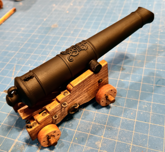
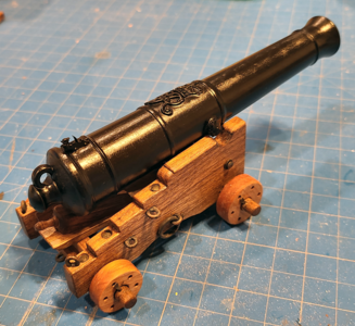
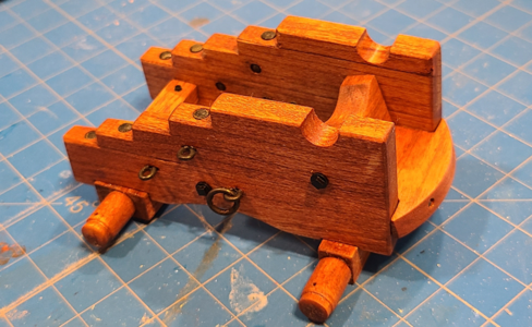
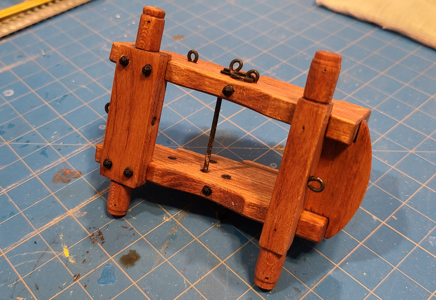
I completed major assembly of the USS Constitution's 24-Pounder carriage, and added hardware:
1670691253051.png
1670691292885.png
The square nuts and washers on the tie bolts are Tichy Train Group #8273. The hex bolts and washers are Meng. The remaining hardware was blackened, but came out irregularly colored, so I will be touching them all up with black paint.

At this point, any hardware related to the capsquares has not been mounted, as I'm unsure how I will be making them, as mentioned previously.

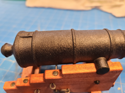
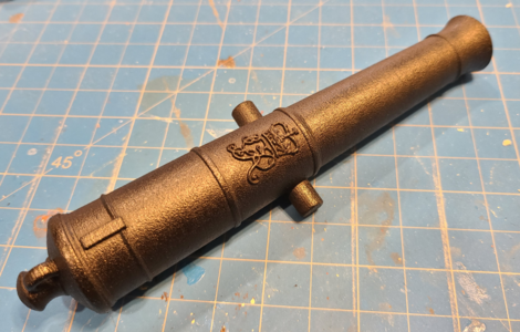
In the end, I decided to go with satin spray on the barrels, and used the spray on the plastic hardware as well. After half a spray on the Constitution's barrel, the spray quit. Not clogged, not empty, the mechanism just failed. I looked around and low-and-behold found a satin spray I already had from some time ago, the cheaper version. Turned out it was actually satin, not splotchy gloss, so it was used on all the barrels. I love the way the barrels came out: as I thought/hoped, the fine grain structure of the SLS 3D print (made from fine grains of plastic) shows through the paint, and gives me a slightly rough cast appearance. Here's a closeup of the result:
1670691659977.png
With this close of a photo, the grain looks too large, and it is actually over scale size. But with the naked eye, I think the appearance is excellent and am extremely happy with my choice. Here's the Victory's 32-pounder barrel:
1670691951646.png
I forgot to drill the touch holes (the 24-pounder had one made into the 3D model), so may give that a try. Hope I don't ruin it, and I don't really want to put a second coat on paint on. As you may notice, I reduced the size and depth of the crest from the oversize version I had on the original resin models. I didn't do any rounding on the details of the crest, as it became too difficult, but think that this casting process did round it slightly, adding to the realism and accuracy IMHO.
 
I completed major assembly of the USS Constitution's 24-Pounder carriage, and added hardware:
View attachment 344870
View attachment 344877
The square nuts and washers on the tie bolts are Tichy Train Group #8273. The hex bolts and washers are Meng. The remaining hardware was blackened, but came out irregularly colored, so I will be touching them all up with black paint.

At this point, any hardware related to the capsquares has not been mounted, as I'm unsure how I will be making them, as mentioned previously.

In the end, I decided to go with satin spray on the barrels, and used the spray on the plastic hardware as well. After half a spray on the Constitution's barrel, the spray quit. Not clogged, not empty, the mechanism just failed. I looked around and low-and-behold found a satin spray I already had from some time ago, the cheaper version. Turned out it was actually satin, not splotchy gloss, so it was used on all the barrels. I love the way the barrels came out: as I thought/hoped, the fine grain structure of the SLS 3D print (made from fine grains of plastic) shows through the paint, and gives me a slightly rough cast appearance. Here's a closeup of the result:
View attachment 344881
With this close of a photo, the grain looks too large, and it is actually over scale size. But with the naked eye, I think the appearance is excellent and am extremely happy with my choice. Here's the Victory's 32-pounder barrel:
View attachment 344889
I forgot to drill the touch holes (the 24-pounder had one made into the 3D model), so may give that a try. Hope I don't ruin it, and I don't really want to put a second coat on paint on. As you may notice, I reduced the size and depth of the crest from the oversize version I had on the original resin models. I didn't do any rounding on the details of the crest, as it became too difficult, but think that this casting process did round it slightly, adding to the realism and accuracy IMHO.
the carriage, looks very nice Okay Exclamation-Mark :)
 
the carriage, looks very nice Okay Exclamation-Mark :)
Thanks very much!

I have a question for any of you who have good knowledge of the HMS Victory's carriages:

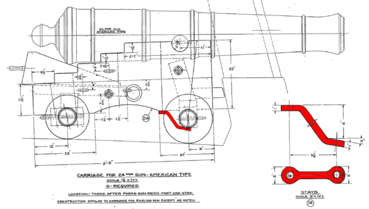
It concerns the fore axletree braces, highlighted in red on this drawing:
1670695053496.png
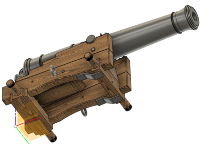
I assumed from this drawing that braces were made of flat iron, more or less a similar size to the capsquares, bent with two holes for the bolts to go through. Like my original CAD model of the 32-pounder shows (less bolts, etc.):
1670696222458.png

However, I see that on the USS Constitution drawings that on its carriage the braces are actually castings or forgings, not bent bar at all:
1670695275072.png
Since the casting is made specifically to size, it does not protrude beyond the bots more than necessary to have sufficient material for strength, while on the Victory's guns it appears to me that they extend further to the fore and aft of the bolts, making me again think they could be just bars rather than castings.

Does anyone know or have photos, etc. that would clarify what was done on the Victory's guns?
 
Back
Top