You are using an out of date browser. It may not display this or other websites correctly.
You should upgrade or use an alternative browser.
You should upgrade or use an alternative browser.
BALDER, Vlaardingen Herring Lugger from 1912, scratch build scale 1:50 Plate-On-Frame
- Thread starter Peter Voogt
- Start date
- Watchers 40
Thanks, Johan. The gray matter has worked quite a few hours.Very nice, especially what's not in the pictures nor the text: the planning; you have to look ahead three or four steps. At least it keeps your grey matter busy and happy...
Regards, Peter
- Joined
- Sep 3, 2021
- Messages
- 4,289
- Points
- 688

Overtime, is my guess.The gray matter has worked quite a few hours.
Dear Peter,Your are more than welcom, Jim. Otherwise I'll grab a chair from the attic:
View attachment 392095
Regard, Peter
I discovered your articles recently and I did bring in my own humble chair...

It is very interesting for me to watch a rivited construction in detail. My model is scaled into 1/64 I had to go only a little step upwards to come towards your scale - interesting fact to watch a Dutch boat not only in 1/55 or 1/44 scale.
- Joined
- Sep 3, 2021
- Messages
- 4,289
- Points
- 688

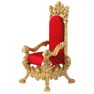
Aha, royalty arrived!I discovered your articles recently and I did bring in my own humble chair...
Hi Christian. With such a chair you are more then welcomeDear Peter,
I discovered your articles recently and I did bring in my own humble chair...
View attachment 414522
It is very interesting for me to watch a rivited construction in detail. My model is scaled into 1/64 I had to go only a little step upwards to come towards your scale - interesting fact to watch a Dutch boat not only in 1/55 or 1/44 scale.
The selection of the scale was related to the chosen material to use. Hope you find some ideas to use.
Regards, Peter
Thanks a lot Peter, I am looking for resources of knowledge due to my torpedo boat builds. I'll follow you with great interest.Hi Christian. With such a chair you are more then welcome
The selection of the scale was related to the chosen material to use. Hope you find some ideas to use.
Regards, Peter
Thanks a lot for your publication.
I would have everytime the fear, that these fragile elements will not stay where they should
one wrong movement with your hand(s) the structure is damaged - my compliment for this unusual work
one wrong movement with your hand(s) the structure is damaged - my compliment for this unusual work
- Joined
- Sep 22, 2023
- Messages
- 173
- Points
- 143

Altissimi livelli, Peter!My intention was to now build the 2nd compartment: the forecastle between bulkheads 51 and 39.
After studying the old drawings, I came to the conclusion that I would be getting myself into trouble.
30 cm behind bulkhead 39 is the mast tube that is also connected to bulkhead 39. And the 'kossing' is also located on the mast tube. This is a triangular box in which the mast approximately 45 dgr can be tilted backwards.
View attachment 411834
(Source: Scheepvaartmuseum Restoration Book, page 27, photo from the Vlaardingen Visserijmuseum collection)
This was done when the ship was 'aan de vleet'. The foremast then picked up less wind, making the ship more stable with only the mizzen sail behind the fishing nets and not pulling on it too hard.
The mast is tilted at an angle of 2 degrees, so that the mast tilts just along the mizzen mast. The mast is therefore not on the keel beam but hinges on a pin at the bottom of the cossing, in the tube.
The tube and kossing are in the middle of the deck. Cutting this in half, just like the hatch on the forepeak, causes even more problems. What do I do with the mast?
The mast tube and kossing will therefore be located in the port side, which will be fully equipped. This means that it will partly protrude beyond the center line. In order to be able to tilt my construction jigs to align the half frames on the flat base plate, I have to make a hole in the base plate, where the mast tube and kossing have fallen. Then I need to know their correct position and how best to cut the bulkhead 39.
So first build that 39 and that tube with kossing. Then I can hold it in any position on my work table for alignment.
The advantage is that after installation, the two will also provide more strength in the longitudinal direction.
The bow section with frames 51 to 54 is now only attached to the keel and under the stringers. With the small floor. That gives some unwanted flexibility in the longitudinal direction.
I added part of the old construction drawing in Photoshop into the drawing of the line plan:
View attachment 411835
A: the mast tube.
B: the 'Kossing'.
At the bottom are the numbers of the frames that are important.
In both drawings I have to keep a close eye on the fact that the deck line on the line plan is the outside of the deck and that on the construction drawing the deck line in the middle of the deck is also decisive.
I have inserted a cutout of the top view at the top left.
It shows that the mast and the front of the hole of the kossing are drawn slightly in the shape of a parallelogram. The front and rear of the mast and cossing run parallel to the deck beams. The sloping sides then left and right.
If the mast were to tilt backwards, the sloping sides would tilt and rotate up and down. That's going to be a problem. Or the mast tube must be wider than the mast base. But then the mast tube loses its effectiveness. It can be seen on the Balder itself and in the restoration specifications that the mast base is square.
View attachment 411836
Also with a rectangular hood as a cover over the opening of the kossing. This point clearly deviated from the specifications drawing.
The old specifications state:
"The mast tube and cossing are composed of sheet material and angle irons. The rear is open. It took some searching and puzzling on the drawings to see what the construction was like.
But this photo also helped:
View attachment 411837
(Source: Maritime Museum Restoration Book, page 68)
A: Kossing.
B: open side of the mast tube.
C: Knees on the frames with deck beams with retaining frames up to the bilge.
D: The frames without deck beam with retaining frames up to the deck.
E: The keelson
F: Sticks placed on the sawn keelson to support the deck.
Made 2 prints and glued them to the right place on the base plate:
View attachment 411838
Then I can use the tilted construction template B to determine the correct position on the base plate A.
Started making watertight bulkhead 39 and the mast tube with kossing:
View attachment 411839
Easy to handle, I was now able to determine 3 important positions correctly:
A: the foot that rests on a plate that comes between the horizontal profiles of the retaining frames 37 and 39.
B: the plates that form the connection between the profile pieces on 39.
C: the profile that will later rest on the deck beam pieces of frames 33, 35 and 37. So I am going to position those deck beams under that profile.
In order to provide longitudinal strength in the open starboard part, the side plate was left loose:
View attachment 411840
A: the port side.
B: the starboard plate.
With the axle on the inside on which the mast base can later be tilted:
View attachment 411841
The dry-fit to see if everything is correct:
View attachment 411842
and what it looks like in position:
View attachment 411843
Now make a hole in the base plate for further alignment and a piece of plate where the angle is set to 88 degrees. To align the kossing at the 2 degrees.
Regards, Peter
Very high standards, Peter!
Thanks for the compliment and your concern, Uwe.I would have everytime the fear, that these fragile elements will not stay where they should
one wrong movement with your hand(s) the structure is damaged - my compliment for this unusual work
It's not that bad. I only have to be careful with temporarily securing it. I do that with wood glue. This means that the pieces of Evergreen only stick together superficially and I can separate them easily and cleanly.
For final gluing I use a glue that softens the Evergeen a bit. It then melts together, as it were, and once dried it is virtually impossible to separate it.
The front part is actually a bit too flexible now. The piece I am going to build now will provide more stability.
Regards, Peter
Thanks, Alessandro.Altissimi livelli, Peter!
Very high standards, Peter!
Regards, Peter
Hi Peter. It is truly amazing again what you show us in this fragile build.
Thanks, Herman. Indeed fragile, and the material is also flexible. But in scale 1:1 the profiles for the frames and other construction parts with a length of a few meters where also. In both scales the combination of joints creates a rigid whole.Hi Peter. It is truly amazing again what you show us in this fragile build.
Regards, Peter
Not had much time to build this week. Again this afternoon. And the plans were immediately adjusted again........
First I had to make the following pieces of stringer plate on the side of the deck. Because that determines the sheer and the curve in the longitudinal direction.
The 2 parts of stringer plate extend to just beyond frame 28.
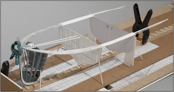
Therefore, I printed the paper template for 28 and applied the stringer plates and the 2x2 corner profiles for the waterways using 2 supports:

This immediately shows why I needed frame 28 and the 2 supports. Otherwise everything will hang down and distort.

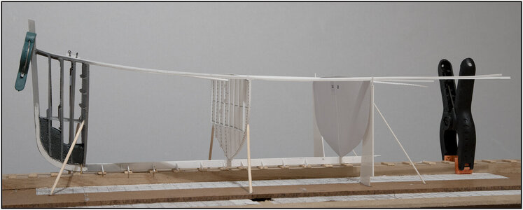
This way the sheer will also show its shape more:
Behind frame 28 the profiles sag a little, but that no longer affects the shape of hull parts.
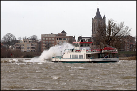
Yesterday storm 'PIA' hit us. That is usually spectacular along the Merwede river along the city of (Wourkum)/Woudrichem. Here is the ferry to Gorcum:

I don't think the captain and mate mind that kind of weather at all.
Regards, Peter
First I had to make the following pieces of stringer plate on the side of the deck. Because that determines the sheer and the curve in the longitudinal direction.
The 2 parts of stringer plate extend to just beyond frame 28.
Therefore, I printed the paper template for 28 and applied the stringer plates and the 2x2 corner profiles for the waterways using 2 supports:

This immediately shows why I needed frame 28 and the 2 supports. Otherwise everything will hang down and distort.

This way the sheer will also show its shape more:
Behind frame 28 the profiles sag a little, but that no longer affects the shape of hull parts.
Yesterday storm 'PIA' hit us. That is usually spectacular along the Merwede river along the city of (Wourkum)/Woudrichem. Here is the ferry to Gorcum:

I don't think the captain and mate mind that kind of weather at all.
Regards, Peter
Last edited:
I never cease to be amazed by your patience and filigree skill. Currently, the structure looks very fragile. How do you deal with it?
Thanks, Stephan. I didn't either.Impressive!
Is the only word I can think about, when looking to what you do with these plastics. I never did or try this way of modeling.
Regards, Peter
Thanks, Jim. I amazed myself to.I never cease to be amazed by your patience and filigree skill. Currently, the structure looks very fragile. How do you deal with it?
Regards, Peter
- Joined
- Sep 22, 2023
- Messages
- 173
- Points
- 143

Ciao Peter, per me le tue spiegazioni e le tue foto (fai benissimo a documentare tutte le fasi in modo progressivo e dettagliato) sono lezioni di modellismo.Not had much time to build this week. Again this afternoon. And the plans were immediately adjusted again........
First I had to make the following pieces of stringer plate on the side of the deck. Because that determines the sheer and the curve in the longitudinal direction.
The 2 parts of stringer plate extend to just beyond frame 28.
Therefore, I printed the paper template for 28 and applied the stringer plates and the 2x2 corner profiles for the waterways using 2 supports:
View attachment 415728
This immediately shows why I needed frame 28 and the 2 supports. Otherwise everything will hang down and distort.
View attachment 415729
This way the sheer will also show its shape more:
Behind frame 28 the profiles sag a little, but that no longer affects the shape of hull parts.
Yesterday storm 'PIA' hit us. That is usually spectacular along the Merwede river along the city of (Wourkum)/Woudrichem. Here is the ferry to Gorcum:
View attachment 415727
I don't think the captain and mate mind that kind of weather at all.
Regards, Peter
Hi Peter, for me your explanations and your photos (you do very well at documenting all the phases in a progressive and detailed way) are modeling lessons.
Hello Peter,
with every update the picture becomes clearer and you can guess what will follow.
Fantastic work and Merry Christmas my friend.
with every update the picture becomes clearer and you can guess what will follow.
Fantastic work and Merry Christmas my friend.


