YUANQING BLUENOSE - Peter Voogt [COMPLETED BUILD]

I made some extra samples for the treenails. The size of 0,5 mm gives me the best view.
Supported by the Saga-info:
The outside of the treenails was 1 3/8" = 1.375" = 34,925 mm.
On scale 1:72 34,925 mm = 0,485 mm = 0,019".
In the drilled holes of 0,5 mm, a toothpick pointed in the Drawplate 22 fits well.
With this result on the finished frame 1, fitted in the keel:
View attachment 213563

I accentuated the treenails with the tip of a auto-pencil which is using 0.5mm fillings:
View attachment 213566
It is depending how flat the light floods over te frame to see more of less of the treenail it self or the accent.
The front and the back of the frame has 1 layer of mat varnish.

I also made a sample with the inside of the hole blackening with the pencil, but it gives no much extra on the view.
Regards, Peter
Does using the varnish limit the final finish on the frames?
 
Because of some issues by the BN-builds of some other builders, I was ready through my own build-log. The I noticed that I have never answered this FI-issue.
But one more thing: on the now oiled planks I did something unorthodox with the treenails. Who knows, may say. Then I tell my FI about that too.
Now I'm intrigued!
Perhaps it also gives Paul the answer to his (by me) never answered question that it is not 'just another BN' .........
It's looking a little plain and ordinary Peter. Any chance you could add some custom details to make it truly yours rather than just another BN?
With the warning of Johan:
Paul,
This comment might come back and haunt you one day, you know that, right?
Johan

I know I'm being called crazy now because it doesn't make any sense, but that's what it said.
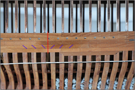
I have clarified it in this earlier posted picture from my build-log:
1216 Nail direction.jpg
The red line shows the separation between frames 35 and 36. Related to this line, the treenails form a V pattern.
My FI: the attachment forces of the planking with the treenails are directed in this way to 1 vertical position on the hull.
Why there ......... no idea.;) It suddenly occurred to me. Could anyone have seen this? I do not think so. Hence this confession. :)
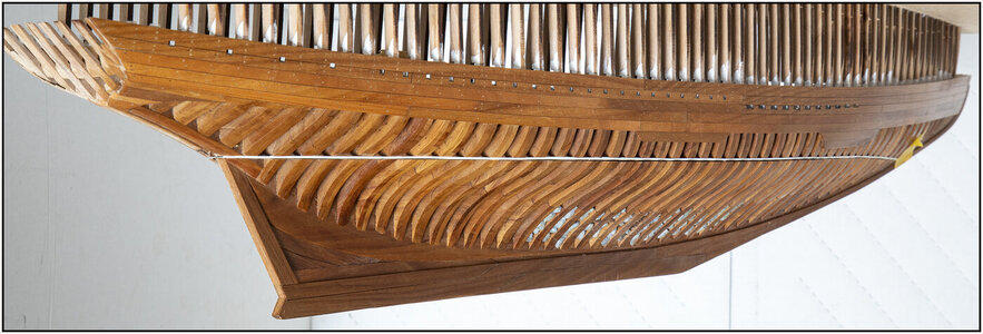
Another picture showing them during the build:
621 Stern.jpg
Perhaps zoom in and search ......
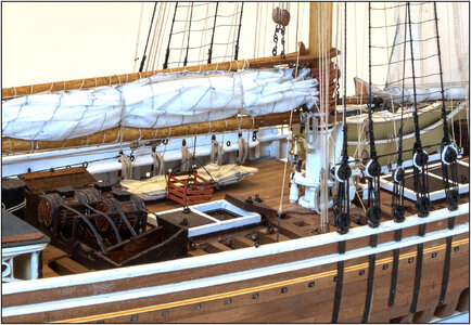
And also on the end result, if you look carefully:
1169 Rope.jpg
As a quoted before ......... It's all in the details ..... :D and AL-FI on it’s best!
Regards, Peter
 
Last edited:
My FI: the attachment forces of the planking with the treenails are directed in this way to 1 vertical position on the hull.
Why there ......... no idea.;)
Nice one Peter, very nice.
One could argue it is to better accommodate the load introduction of the hull's bending loads, either upwards or downwards, but that might be a rather slippery slope.
Btw, did you give the port side the same treatment?
 
Nice one Peter, very nice.
One could argue it is to better accommodate the load introduction of the hull's bending loads, either upwards or downwards, but that might be a rather slippery slope.
in any case it stimulates the why ……..
Btw, did you give the port side the same treatment?
Yes, but you have to look very carefully there because it is black and red.
Regards, Peter
 
C'è una cura dei particolari assolutamemte fantastica.
Rimango assolutamente ammirato da questo lavoro Peter.
Tu e Johan siete modellsiti eccezionali, portate in alto la vostra bandiera.

There is absolutely fantastic attention to detail.
I remain absolutely in awe of this work Peter.
You and Johan are exceptional naval modellers, fly your flag high.
 
Brilliant!
I second that
C'è una cura dei particolari assolutamemte fantastica.
Rimango assolutamente ammirato da questo lavoro Peter.
Tu e Johan siete modellsiti eccezionali, portate in alto la vostra bandiera.

There is absolutely fantastic attention to detail.
I remain absolutely in awe of this work Peter.
You and Johan are exceptional naval modellers, fly your flag high.
The details of your BN continue to amaze me, Peter.
Thanks for your reactions with the compliments.
For some reason I just spent the last several minutes trying to imagine what type of forces did real treenails undergo, bending, shear, tension....
they scream: - Stop hitting me in the head!!! ROTF ROTF ROTF
When you see the ship in front of you, rolling, pitching and pounding in a rough sea, it groans and groans at every seam. Then the treenails in the planks have their say: this is why you hit us, now we keep you safe. How small nails become great.
Regards, Peter
 
The details of your BN continue to amaze me, Peter. For some reason I just spent the last several minutes trying to imagine what type of forces did real treenails undergo, bending, shear, tension....
The treenails themselves can only take bending, shear and surface pressure. The hull itself would be subject to bending-, tension-, compression- and torsional loads (am I forgetting one or two?). I can't really think of a dominant load case, requiring the treenails to reverse at one point or another.
Like Peter said: Free Interpretation.
 
Nevertheless, it is advisable to continue to read the manual from time to time. For the last low deck beam, I noticed another small gap between the bearing beams:
View attachment 266047
Left with space and right filled in.

For the lesson for the other builders:
In the manual on page 16, photo 90 shows the bar '45', fitted agains deck beam 26:
View attachment 266048
And for the sake of completeness: On pages 18 and 19 in photos 109 and 110 the bar '105' is shown. This will come later in front of deck beam 27, on the planks of the foredeck and will be sanded with the top of the planks of the aft deck.
Regards, Peter
Thanks that got it into perspective
 
All in all, the spacers went in smoothly. Everything Dry-Fit, because a final placement will follow on the deck later.
Then the inside can now be sanded so that the frames comes in a smooth line. So that the inner beams (and partial planking) can be installed with a smooth connection. The spacers give the frames more strength halfway and especially at the thin single parts.
The hull feels comfortably strong now.
From 3 points of view, the last one shows her beautiful curves. The sanding of the outside will (probably) come later. But yeah.....you never know......
View attachment 237455
View attachment 237456
View attachment 237457
There is no pain, you are receding
A distant ship smoke on the horizon
You are only coming through in waves
Your lips move but I can't hear what you're saying
When I was a child I had a fever
My hands felt just like two balloons
Now I've got that feeling once again
I can't explain, you would not understand
This is not how I am
I have become comfortably numb​
(Yes, a long time ago I played that as a soloist on my E-flat tuba)
Regards, Peter
I'm at the waterway temporary install stage. Could you please let me know what you used to glue them in place to be temporary?
Macro shots have advantages and disadvantages. You see everything. ;)
So I wasn't completely satisfied with what I saw now (even better). Adjusted a few things.

View attachment 240035
The bearing beam #102 runs against frames 1 to 27.
Not all 27 notches will be exactly aligned in a row. Therefore 5 temporary deck beams placed over an equal distance. With the advantage that I can press the beam against it when gluing in to get into place. Because only visually will not work;
All the holes for the nails marked and pre-drilled. Like the keelson, this is a beam that should give strength to the construction. So also with each frame 2 nails, both one in the front and the rear frame part.

View attachment 240036
The connection at the front to the keelson was not neat (enough). So a little extra sanding.

View attachment 240037
Looking a bit ahead at the connection of both beams to the middle deck. Made a small chamfer between the connecting parts because the space between the lower (#102) and upper (#103) beam was just not the thickness of a beam. It's not much, but enough to not fit correct.

Regards, Peter
 
I'm at the waterway temporary install stage. Could you please let me know what you used to glue them in place to be temporary?
Hi Ted. As you can see on the pictures and what I wrote:
All in all, the spacers went in smoothly. Everything Dry-Fit, because a final placement will follow on the deck later.
So, no glue, otherwise you can’t use them later. Just in place by friction or some small pieces of tape.
Now you use them as spacers that hold the frames in position lengthwise when you installed the bearing beams. After that you take them out and use them later on top of the deck as waterways.
For permanent bonding of the wood parts I only used PVA.
Regards, Peter
 
Last edited:
Hi Ted. As you can see on the pictures and what I wrote:
All in all, the spacers went in smoothly. Everything Dry-Fit, because a final placement will follow on the deck later.
So, no glue, otherwise you can’t use them later. Just in place by friction or some small pieces of tape.
Now you use them as spacers that hold the frames in position lengthwise when you installed the bearing beams. After that you take them out and use them later on top of the deck as waterways.
For permanent bonding of the wood parts I only used PVA.
Regards, Peter
Thank you Peter.
Your photos provided a wealth of information to compliment the dialogue in your messages and build log.
Ted
 
Back
Top