- Joined
- May 1, 2023
- Messages
- 112
- Points
- 113

Rigging - Channels, Dead-eyes, Gaff and Driver boom
Channels & Dead-eyes
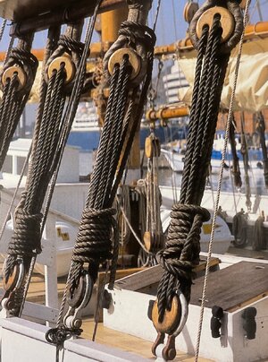
There isn't much I can say about channels and dead-eyes here. However, since these elements are very visible on each model, I think it's worthwhile to see how they look on a real ship. The only thing worth noting is that all the rigging now, given that the ship obviously has not sailed for a while, looks much more 'tired' than it did when it was newly restored and began its new era voyages. Here are some pictures from the Book, showcasing those golden times. Compare them with other pictures I took recently.
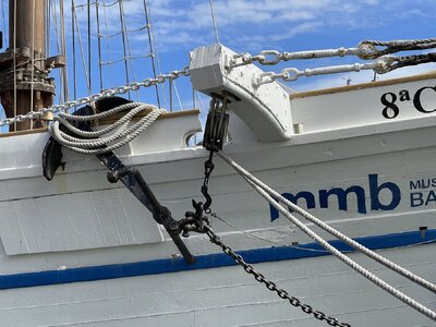
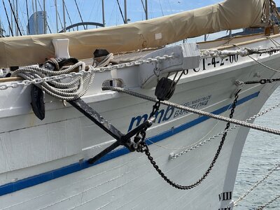
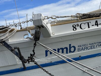
Now, take a look at these freshly taken pictures and see the difference. For example, notice the dead-eyes painted black. Although, in general, I think all the ropes are tied correctly, she would hardly manage at sea without a thorough inspection and significant renovation of all parts of the rigging.
Channels and dead-eyes from outside (starboard):
Fore channel, dead-eyes and lower part of shrouds
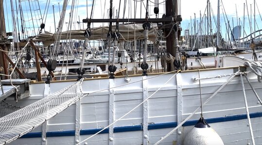
Main channel, dead-eyes and lower part of shrouds
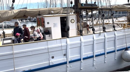
Mizzen channel, dead-eyes and lower part of shrouds
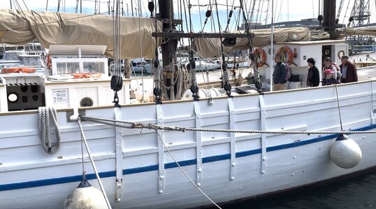
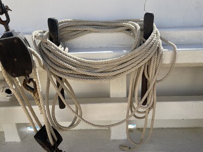
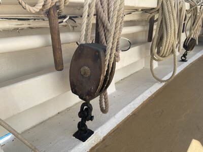
Fore dead-eyes and some ropes, starboard from inside:
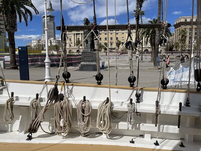
and portside from inside:
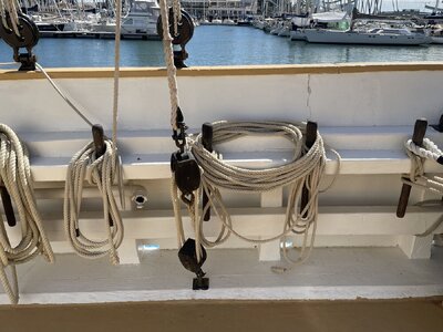
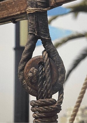
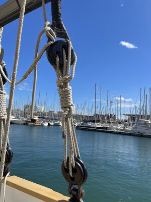
A couple of dead-eyes closeups:
Gaff and driver boom
Now lets' say a couple of words about Gaff and Boom. This is just a good case to compare classic literature and reality
This is what zu Mondfeld says about how the gaff and boom were fixed to the mast:
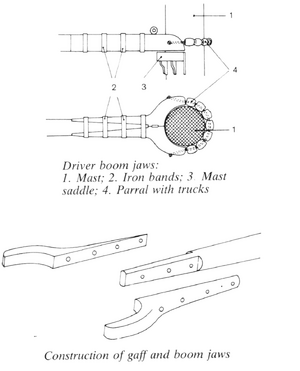
"In the second half of the 18th century the mizen yard was cut short at the mast, and the remaining upper part was fixed to the mast with a fork known as the jaws. A horizontal boom was then fitted at the bottom of the mast to enable the gaff sail to be fully deployed. This a ended in jaws, which rested on a saddle on the mast. The gaff and the driver boom jaws were held to the mast with a simple parral with trucks.
In the 19th century the jaws were superseded by goosenecks. The driver boom sometimes carried foot ropes, and various means of fitting a studding sail or ringtail were also tried. Like the lateen yard, the gaff and driver boom were not symmetrical around their thickest point, which is a point worth noting if you are aiming at an outstandingly accurate model."
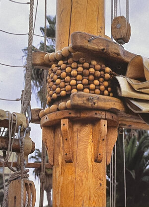
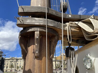
But on the real Santa Eulàlia, built in the 20th century (even though today what we see is just a replica, many pictures of this and similar ships remain), we can clearly see jaws, but not the joint called 'goosenecks'. It's also worth noting that on ships of this type, all masts (in this case, all three) had similar rigging and sails.
This is what I wanted to share today.
Have a great time of day and stay tuned
Channels & Dead-eyes
There isn't much I can say about channels and dead-eyes here. However, since these elements are very visible on each model, I think it's worthwhile to see how they look on a real ship. The only thing worth noting is that all the rigging now, given that the ship obviously has not sailed for a while, looks much more 'tired' than it did when it was newly restored and began its new era voyages. Here are some pictures from the Book, showcasing those golden times. Compare them with other pictures I took recently.
Now, take a look at these freshly taken pictures and see the difference. For example, notice the dead-eyes painted black. Although, in general, I think all the ropes are tied correctly, she would hardly manage at sea without a thorough inspection and significant renovation of all parts of the rigging.
Channels and dead-eyes from outside (starboard):
Fore channel, dead-eyes and lower part of shrouds

Main channel, dead-eyes and lower part of shrouds

Mizzen channel, dead-eyes and lower part of shrouds

Fore dead-eyes and some ropes, starboard from inside:

and portside from inside:


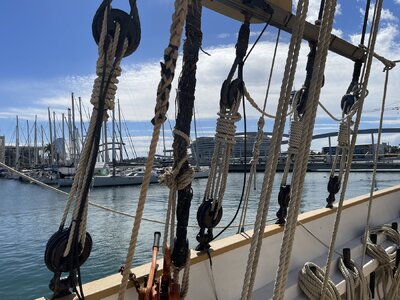
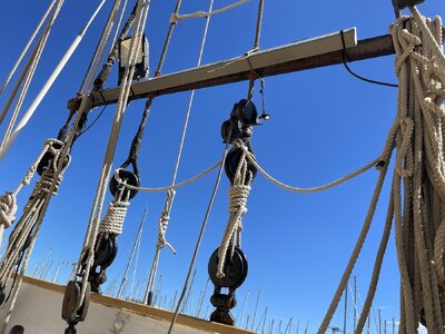
A couple of dead-eyes closeups:


Gaff and driver boom
Now lets' say a couple of words about Gaff and Boom. This is just a good case to compare classic literature and reality
This is what zu Mondfeld says about how the gaff and boom were fixed to the mast:
"In the second half of the 18th century the mizen yard was cut short at the mast, and the remaining upper part was fixed to the mast with a fork known as the jaws. A horizontal boom was then fitted at the bottom of the mast to enable the gaff sail to be fully deployed. This a ended in jaws, which rested on a saddle on the mast. The gaff and the driver boom jaws were held to the mast with a simple parral with trucks.
In the 19th century the jaws were superseded by goosenecks. The driver boom sometimes carried foot ropes, and various means of fitting a studding sail or ringtail were also tried. Like the lateen yard, the gaff and driver boom were not symmetrical around their thickest point, which is a point worth noting if you are aiming at an outstandingly accurate model."
But on the real Santa Eulàlia, built in the 20th century (even though today what we see is just a replica, many pictures of this and similar ships remain), we can clearly see jaws, but not the joint called 'goosenecks'. It's also worth noting that on ships of this type, all masts (in this case, all three) had similar rigging and sails.
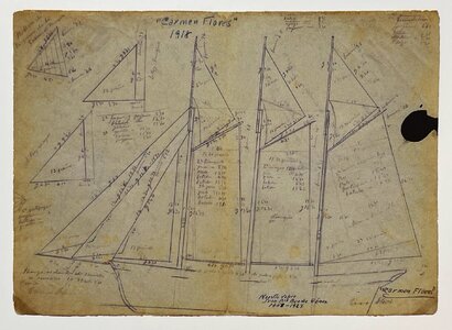
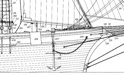
Here is the picture from the Book:
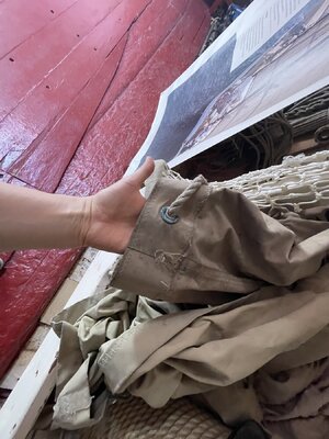
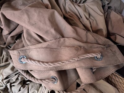
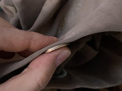
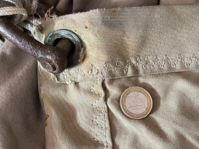
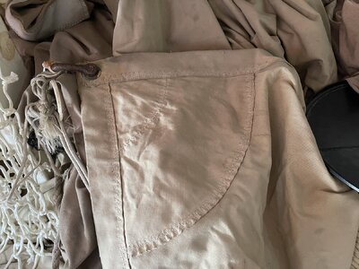
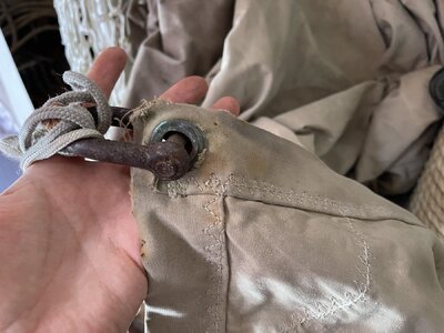
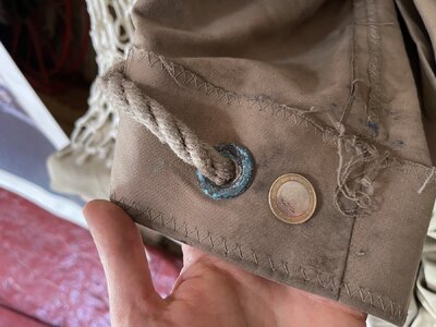
And some other pictures of gaffs and related ropes, I took
(the coin is 2 EUR):
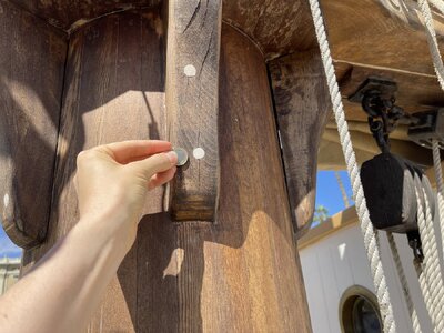
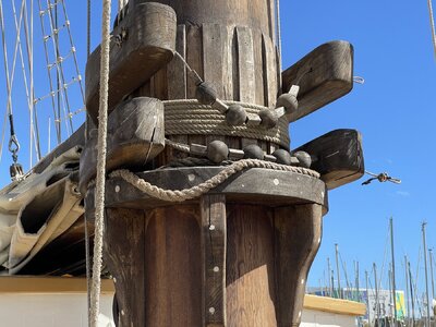
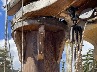
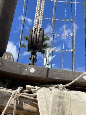
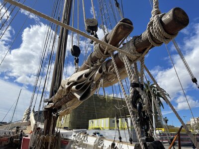
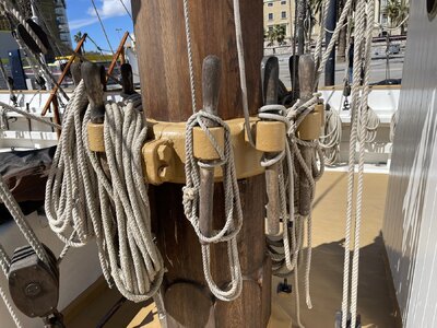
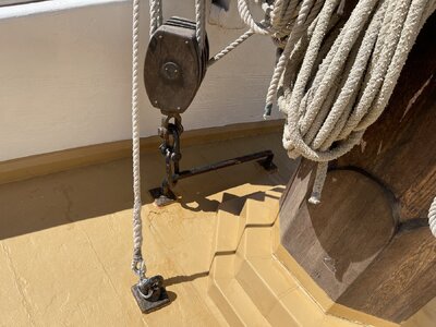
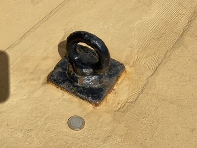
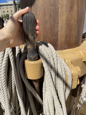

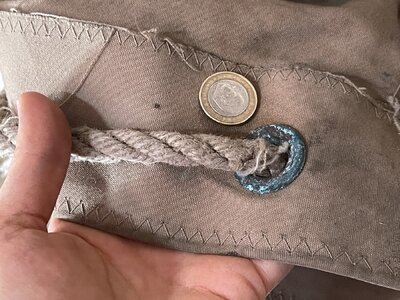
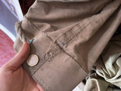
And some other pictures of gaffs and related ropes, I took
(the coin is 2 EUR):


This is what I wanted to share today.
Have a great time of day and stay tuned
Last edited:

