- Home
- Forums
- Ships of Scale Group Builds and Projects
- Le Coureur 1776 1:48 PoF Group Build
- Le Coureur 1776 1:48 Group Build Logs
You are using an out of date browser. It may not display this or other websites correctly.
You should upgrade or use an alternative browser.
You should upgrade or use an alternative browser.
LE COUREUR - french Lugger 1776 - POF kit from CAF in 1:48 by Uwe
An interesting action that happened when I was firing my small blackpowder cannon, viewed in very slow motion, was that the carrige would "leap" up and backwads when the shot was fired. The breach was not elevated very highly to drive the carriage downwards. Leaping guns with tons of weight would definately be a hazzard if a full sized gun would recoil in the same manner. Nice work on your part. Rich (PT-2)My friends,
many thanks for all your comments, hints and remarks - and off course also for the received likes
Before I started with the guns, I made the preparations on the hull, means the installation of the bolts for the gun tackles visible outside of the hull.
Here the manual descriptions for your information
View attachment 258730
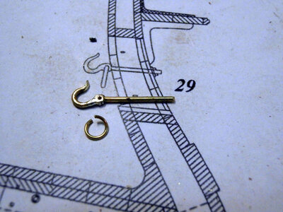
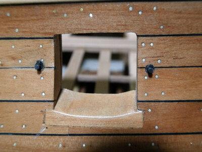
shown are two bolt ends located at each side of the gunports - the upper one for the ringbolt for the tackle and the lower ones for the hooks of the breeching rope
View attachment 258731
View attachment 258732
The inner ringbolt and hook I decided to install later on together finally with the guns - it is much easier to prepare the complete tackle incl. the ringsbolts and hooks at the gun, compared to the necessary work to fix the tackle, when they are already installed at the railing.
As usual I compared the bolt solution with the Boudriot monograph
View attachment 258733
and photos showing scratch build models
View attachment 258740
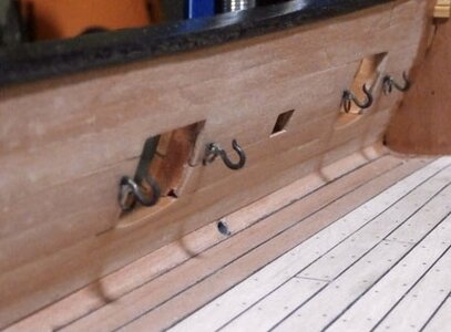
and realized, that there are outside only two bolts at each gunport visible
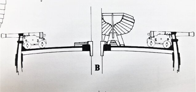
closer look at the Boudriots drawing of the Le Coureur is showing us a different type of fixing the gun tackles and breeching rope - unfortunately no sideview
View attachment 258734
Only with this drawing I did not understand, how this bolt could look like (nowhere else in the monograph is shown something), but I found the final missing info in the monograph of the Le Cerf also by jean Boudriot.
View attachment 258741
so it is a combined hook with implemented ring
Once more it is getting clear, that the recoil forces of such 2 and 3pdr guns was not very high.
From technical point of view I have my doupts (this is now brainstorming), if such a combined ring-hook was really working well ?!?!
Usually on bigger or other guns the fixing points were organized like this:
The hook or bolt for the breeching rope is lower installed than the ringbolt for the gun tackle! So the tackle of the gun was everytime free to remove from the hook or not covered by the breeching rope
View attachment 258744
I am sure it was partly problematic with such a ring hook
View attachment 258745
beacuse here the ring for the tackle (green) is installed under the hook of the breeching rope (red)
View attachment 258746
see also the photos of a Le Cerf model
View attachment 258743 View attachment 258742
I guess it was sometimes no easy to handle and the ropes were sometimes, after the gun recoiled, not easy to get free or to handle......
Sorry for the longer and maybe for a lot members uninteresting subject, but I am still thinking about to make one combined or two seperate fixing points........
Many thanks to all of you for your comments, information hints and brainstorming - still open for comments off course.
It seems, that such combined hooks were used on french smaller ships (like the Cerf, Amaranthe etc.
Nevertheless I have also my doupts, if I am able to produce 16 of such hooks with an acceptable quality.
My first attempt using a hook and adjust it was failing, so in momenr I do not see a good solution. I guess also, that the best would be casting some.
But I have some more time to decide and produce, until I finally fix the guns on the deck
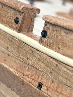
For now I made only one level of iron bolts on the outer side of the hull close to the gunports
I used the small rings of the photo etched sheet and a 0,8mm brass wire pieces
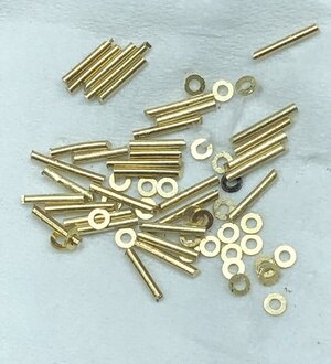
blackened these parts
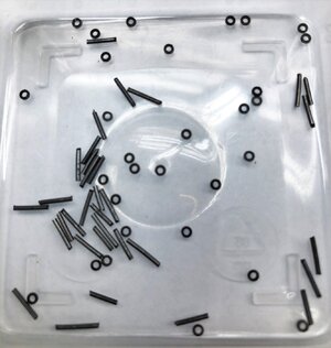
and glued them together
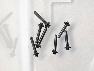
and these "bolts" are now looking like these
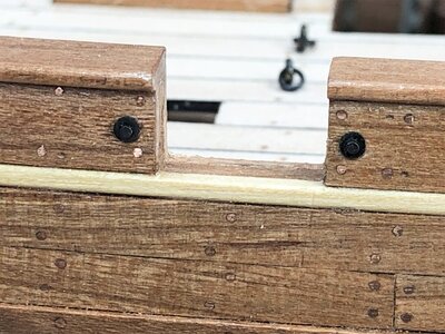
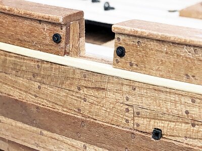
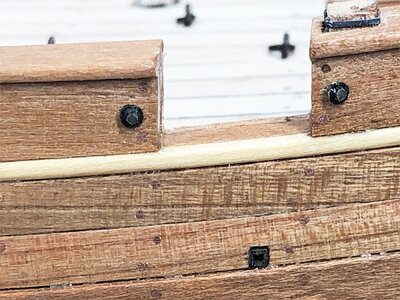
and a better view from the side - I think they are looking realistic
It seems, that such combined hooks were used on french smaller ships (like the Cerf, Amaranthe etc.
Nevertheless I have also my doupts, if I am able to produce 16 of such hooks with an acceptable quality.
My first attempt using a hook and adjust it was failing, so in momenr I do not see a good solution. I guess also, that the best would be casting some.
But I have some more time to decide and produce, until I finally fix the guns on the deck
For now I made only one level of iron bolts on the outer side of the hull close to the gunports
I used the small rings of the photo etched sheet and a 0,8mm brass wire pieces

blackened these parts

and glued them together

and these "bolts" are now looking like these


and a better view from the side - I think they are looking realistic

Very nicely executed work here. May I ask what the scale of the ship is? Also the treenails as I will be using something probably smaller on my Kryenia boat to simulate the same for the mortise and tenon hull strakes which were not "nailed" to frames but created a shell for the gull itself.Many thanks to all of you for your comments, information hints and brainstorming - still open for comments off course.
It seems, that such combined hooks were used on french smaller ships (like the Cerf, Amaranthe etc.
Nevertheless I have also my doupts, if I am able to produce 16 of such hooks with an acceptable quality.
My first attempt using a hook and adjust it was failing, so in momenr I do not see a good solution. I guess also, that the best would be casting some.
But I have some more time to decide and produce, until I finally fix the guns on the deck
For now I made only one level of iron bolts on the outer side of the hull close to the gunports
I used the small rings of the photo etched sheet and a 0,8mm brass wire pieces
View attachment 258882
blackened these parts
View attachment 258883
and glued them together
View attachment 258884
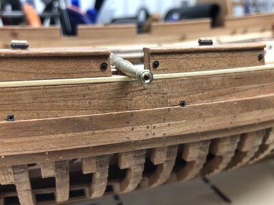
and these "bolts" are now looking like these
View attachment 258885
View attachment 258886
View attachment 258887
and a better view from the side - I think they are looking realistic
View attachment 258888
Rich (PT-2)
That's the hook, man! How was it made, that's my question.Hello Uwe, L‘Amarante also has this ring / hook combination
View attachment 258802
View attachment 258803
That looks like some patient bending, hammering and filing to shape before drilling the hole for the ring. Must be in a small scale, large piece, size. Just thinking . . . ?????That's the hook, man! How was it made, that's my question.
Based on the hint with the Amarante made by Tobias - we do not have to look so far awayThat's the hook, man! How was it made, that's my question.
In detail shown in the building log of the amazing 1:30 model of the L´ Amarante made by our member Gianpiero alias @Giampy65
Link to the building log:
I guess it is ok for him to use his photos and copy his photos once more here in this log, so you can see the work - highly interesting and a very good result...... off course they are bigger than our becessary hooks in 1:48, but it would be a solution to produce them in scratch
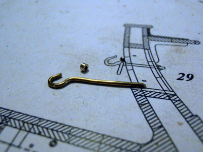
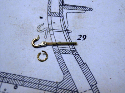
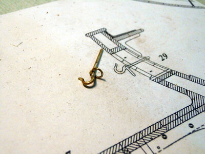
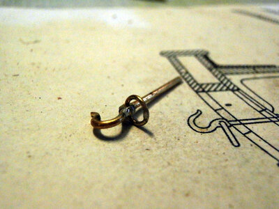
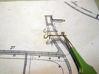
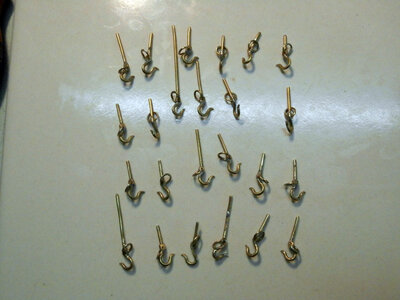
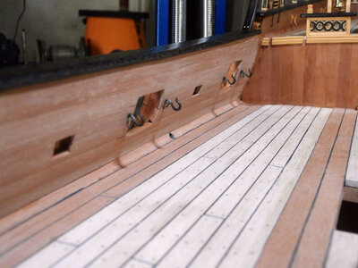
Very good work !!!
Hope to see soon also more on his @Giampy65 ´s actual project of the Swan class HMS Pegasus in 1:36
H.M.S. PEGASUS - Swan Class by David Antscherl & Greg Herbert Scale 1:36
As I had anticipated, I started a new challenge: the construction of an English frigate, with a carpentry that, until now, I had never approached. Very fascinating architecture, and a model, the Pegasus that struck me immediately, already from the first splendid images seen. I am studying a lot...
shipsofscale.com
Hallo Rich,Very nicely executed work here. May I ask what the scale of the ship is? Also the treenails as I will be using something probably smaller on my Kryenia boat to simulate the same for the mortise and tenon hull strakes which were not "nailed" to frames but created a shell for the gull itself.
Rich (PT-2)
the scale is 1:48
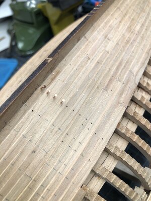
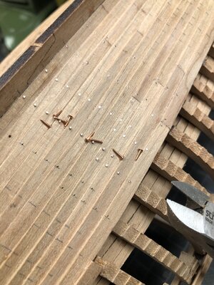
The treenails you mentioned, and I guess you mean the hull planking and not deck are (better to say) boltings and not wooden treenails. The french used for such clinker built hulls mainly bolts to fix the planks - I was using here small copper nails with diameter 0,5 mm for the planking and 0,6 mm for the wales.
Just checked the posts in my log - I started with the preparation and the nailing this February, so if you are interested in more details please check the lengthy descriptions starting from here:
LE COUREUR - french Lugger 1776 - POF kit from CAF in 1:48 by Uwe
Like a Nudelwalker :D
shipsofscale.com
Thanks for the process and link. I'll look at that. My pending need will be very small in dimensions of the 1:43 scale as in the actual 1:2 the tennons were spaced 12 cm apart side by side and with anchoring pegs 6 cm above and below each strake fastening them together. The tennons were staggered between those above and the next one below in a Z type of layout for the lengths of every strake. Taking 12 cm full size down to 1/43 scale is a very small dimension and lots of those simulated treenail pegs which were then also set with a copper nail being driven into the end. What copper nailing that was done was driving fhrough members and clinched on the interior face with a long and shorter leg making a type of U shape to the inside nail shape which I will likely have to disregard and not execute. 1:43 is a larger boat than 1:48 but still a small size for me to work with. RichHallo Rich,
the scale is 1:48
The treenails you mentioned, and I guess you mean the hull planking and not deck are (better to say) boltings and not wooden treenails. The french used for such clinker built hulls mainly bolts to fix the planks - I was using here small copper nails with diameter 0,5 mm for the planking and 0,6 mm for the wales.
Just checked the posts in my log - I started with the preparation and the nailing this February, so if you are interested in more details please check the lengthy descriptions starting from here:
LE COUREUR - french Lugger 1776 - POF kit from CAF in 1:48 by Uwe
Like a Nudelwalker :Dshipsofscale.com
View attachment 259074 View attachment 259075
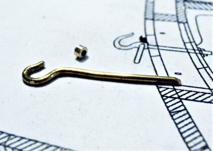
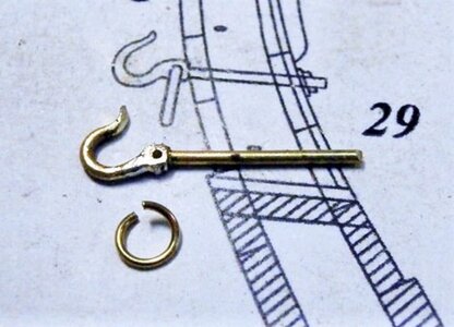
I have still some time until the inner hook question has to be decided, nevertheless I will try once the way shown by @Giampy65 with the additional "material" - some experiments have to follow
So definitely some time to start with the "main guns" of the Le Coureur.
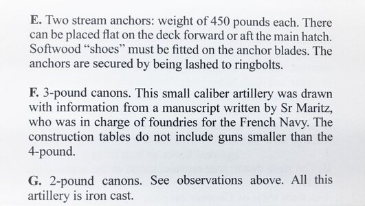
the words by Jean Boudriot....
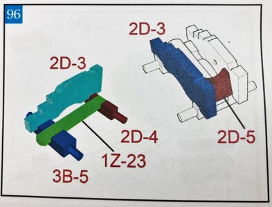
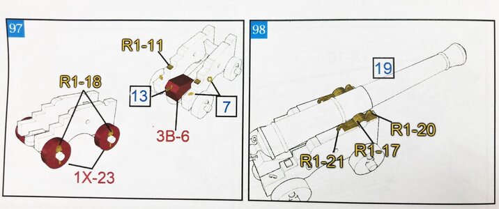
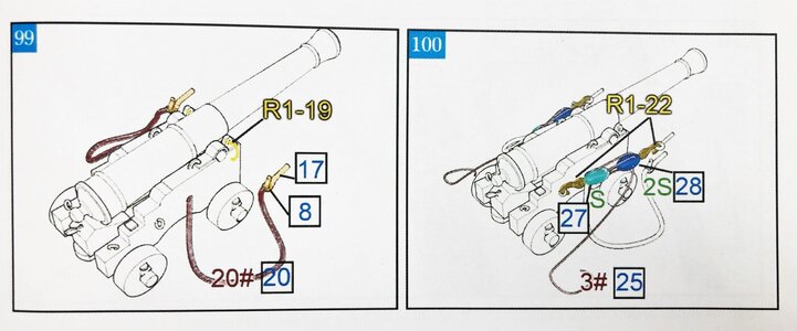
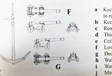
and here as usual the sketches in the manual
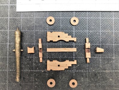
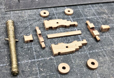
The different parts of the guns are well prepared and of very good material quality
I started first the assembly of one gun in order to test the different working steps. Afterwards, when everything is tested I am able to start the "mass-production" of the remaining seven guns
I first step was done - so I will now make the other seven wooden gun carriages - until now no "metal" works done


So definitely some time to start with the "main guns" of the Le Coureur.
the words by Jean Boudriot....

and here as usual the sketches in the manual


The different parts of the guns are well prepared and of very good material quality


I started first the assembly of one gun in order to test the different working steps. Afterwards, when everything is tested I am able to start the "mass-production" of the remaining seven guns


I first step was done - so I will now make the other seven wooden gun carriages - until now no "metal" works done
Your canons are on the right way, Uwe. Please, can you show me Giampy´s post if availible ?
link and copy of photos in my post #1047 of this topic...... scroll shortly backwardsYour canons are on the right way, Uwe. Please, can you show me Giampy´s post if availible ?
Dankeschön. Habs überlesen.
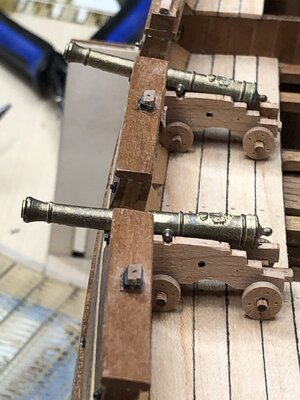
The length of the barrel looks too long for the carriage but I recall that some calibers were cast with long barrels. It looks nice in place. RIchI have still some time until the inner hook question has to be decided, nevertheless I will try once the way shown by @Giampy65 with the additional "material" - some experiments have to follow
View attachment 259555 View attachment 259556
So definitely some time to start with the "main guns" of the Le Coureur.
the words by Jean Boudriot....
View attachment 259560
and here as usual the sketches in the manual
View attachment 259557
View attachment 259558
View attachment 259559
The different parts of the guns are well prepared and of very good material quality
View attachment 259561
View attachment 259562
I started first the assembly of one gun in order to test the different working steps. Afterwards, when everything is tested I am able to start the "mass-production" of the remaining seven guns
View attachment 259563
View attachment 259564
View attachment 259565
I first step was done - so I will now make the other seven wooden gun carriages - until now no "metal" works done
These guns were only 3pdr guns, so relatively light barrels or muzzles.The length of the barrel looks too long for the carriage but I recall that some calibers were cast with long barrels. It looks nice in place. RIch
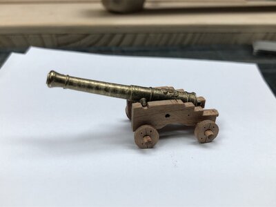
The 1:48 version muzzle is full casted and not rebored, so in moment they bent forward (you will se this soon in some photos) - I tried to drill them out, to make them lighter in the front part, but a drop of glue will make the deal at the end.
The design of muzzle and carriage are confirmed in detail by Jean Boudriot, who was a real specialist in all kind of naval gunnery and weapons, shotguns etc.
Book review - NAVAL ARTILLERY French navy 1650-1850" - NEW ENGLISH VERSION - by Jean Boudriot and Hubert Berti
Book Review: NAVAL ARTILLERY French navy 1650-1850 An Historical and Technical Study Set of 93 plates. NEW ENGLISH VERSION by Jean Boudriot and Hubert Berti Translated by François Fougerat This book in french language was over a long time one of the Basic Books published by ancre...
shipsofscale.com
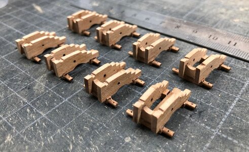
so step by step I am working on the guns - first finishing the wooden works on the eight carriages
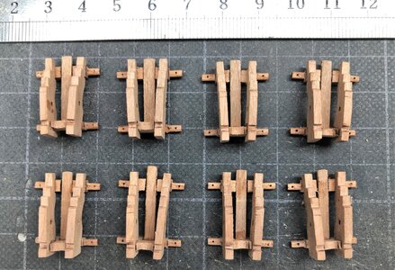
and the wheels - I made with a knife the hal cut and with a spike I tried to immitate the small bolts
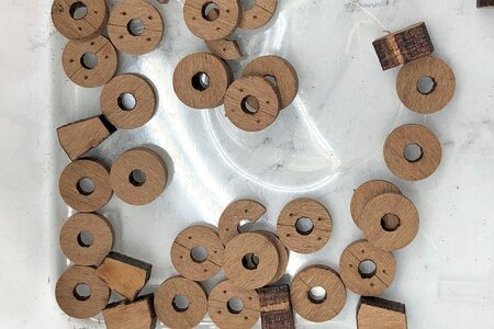
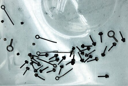
aftwards I blackened the small pins to fix the wheels (and also the necessary eyebolts for later) - the heads of the pins are appr.1mm
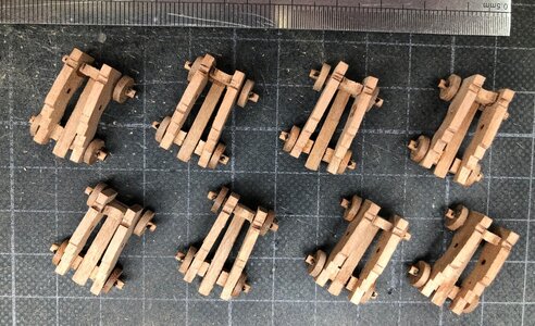
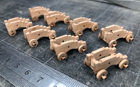
the small pins have to be bended by 90° before the blackening
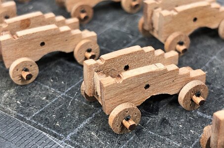
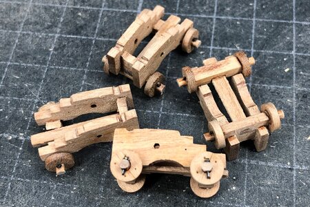
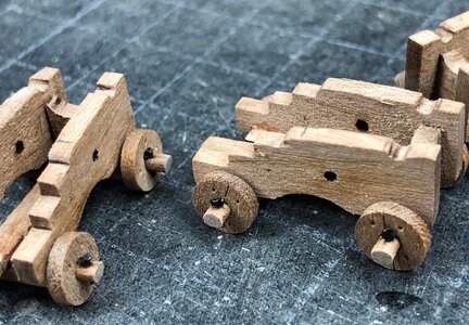
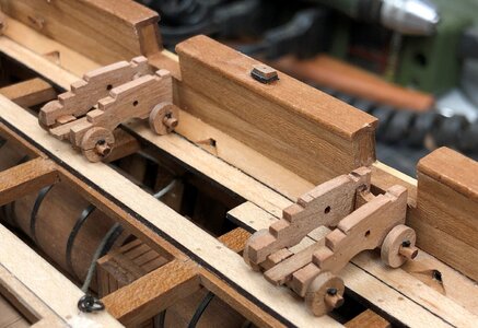
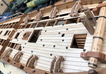
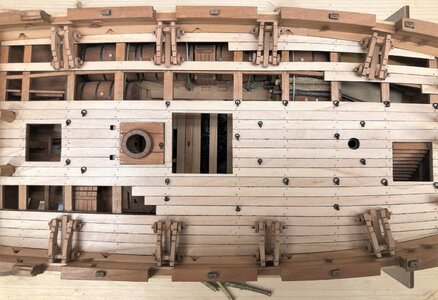
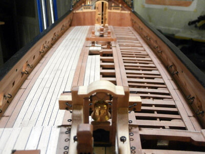
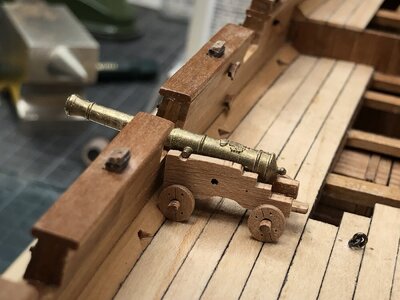
Now we can see, that all the wheels of the guns will stand on top of the deck planking - this was also part of the preparation of the deck planking months ago with the help of the gun-paper-dummies
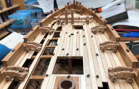


and the wheels - I made with a knife the hal cut and with a spike I tried to immitate the small bolts


aftwards I blackened the small pins to fix the wheels (and also the necessary eyebolts for later) - the heads of the pins are appr.1mm


the small pins have to be bended by 90° before the blackening


Now we can see, that all the wheels of the guns will stand on top of the deck planking - this was also part of the preparation of the deck planking months ago with the help of the gun-paper-dummies

Coming along nicely Uwe. Are you chemically blackening the brass cannon barrels, or leaving them brass ?
Wonderful clean work, looks very, very good.
but before I finish the finish of the muzzles I had to finish or prepare the iron parts on the carriages - once more first on the trial carriage (No. 1 of 8)
the rings of the tackles were blackened and installed as well the small heads of the vertical bolts (they are appr. 0,5mm square - you see the toothpick on the right side
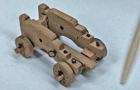
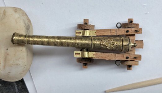
here the carriage with a muzzle and the two capsquares
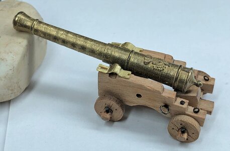
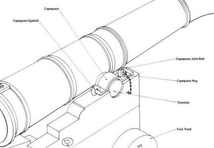
This here is an excerpt sketch showing the detail of the typical fixing of the muzzle on the carriage - the capsquare with all elements
With the top view (two photos above) we can see, that the brass part of the kit are slightly too big - so I tried to reduce either the length and also the width by sanding - on the following photo -> the lower one on the carriage is slghtly adjusted, the above one is original
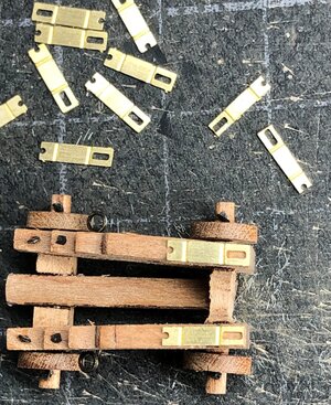
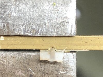
Now I had to think of how to bend this small flat capsquare - I first try with round pliers was not very nice and took to much time, so I had to try something else
my final solution simple but very effective:
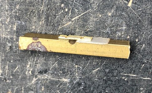
I used a square brass bar and sanded in 90° a semicircle notch - a small piece of double sided tape fixed the flat capsquare
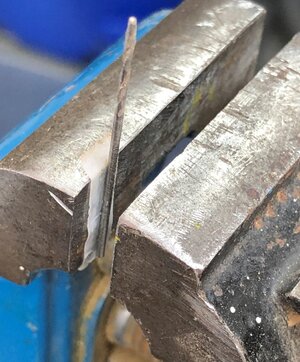
and this was my simple counter - a drill bit fixed with tape on my smallest bench vise
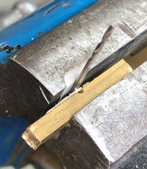
and finished was my bending tool
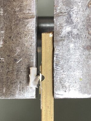
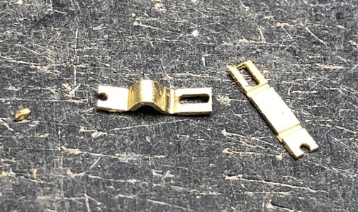
and the final result
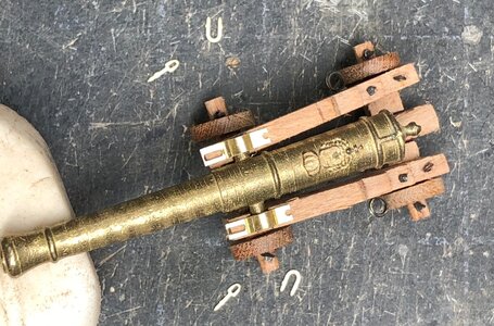
also on the carriage you can see the capsquare joint bolts and the capsquare eyebolt
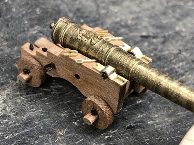
the rings of the tackles were blackened and installed as well the small heads of the vertical bolts (they are appr. 0,5mm square - you see the toothpick on the right side

here the carriage with a muzzle and the two capsquares


This here is an excerpt sketch showing the detail of the typical fixing of the muzzle on the carriage - the capsquare with all elements

With the top view (two photos above) we can see, that the brass part of the kit are slightly too big - so I tried to reduce either the length and also the width by sanding - on the following photo -> the lower one on the carriage is slghtly adjusted, the above one is original

Now I had to think of how to bend this small flat capsquare - I first try with round pliers was not very nice and took to much time, so I had to try something else
my final solution simple but very effective:
I used a square brass bar and sanded in 90° a semicircle notch - a small piece of double sided tape fixed the flat capsquare

and this was my simple counter - a drill bit fixed with tape on my smallest bench vise

and finished was my bending tool


and the final result


also on the carriage you can see the capsquare joint bolts and the capsquare eyebolt


