HM Sloop Fly, 1776 - scale 1/36 by own reconstruction and the books from David Antscherl

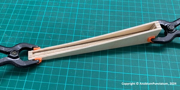
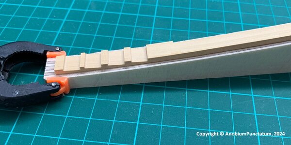
Today I glued the prepared parts of the deadwood halves together.
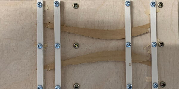
Before I can start I have to clean the round notches. I milled a small holder for the second component. I can use this to align the component parallel to the milling plane in the vice.
Fly-016.jpg

Fly-017.jpg

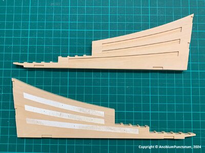
For glueing the parts together I use thinner template in the notches than shown in the last part of the log. With I can turn the compenent for drying. This is a lesson I learned from my Alert build. The timber is milled very well but there are allways little differences. The following picture shows both halves. In the bottom halve you can see the template.
Fly-018.jpg

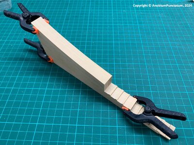
After removing the small templates I clipped the original templates in the notches and checked if everything fit together.
Fly-019.jpg

Tomorrow it will rain, so I will have time to start with the complicated part of the deadwood - milling the recesses for the foremost and rearmost frames and the steps of the cant frames
 
As the after deadwood is much more complicated, I started with milling the two parts of the fore deadwood. For milling the parts, I prepare a small jig to fix the deadwood halves. First, I use the wo inner positions and mill the outer parts. I use than the outer brackets and mill all other parts of the deadwood.
The following picture shows the parts with all four brackets.
Fly-020.jpg

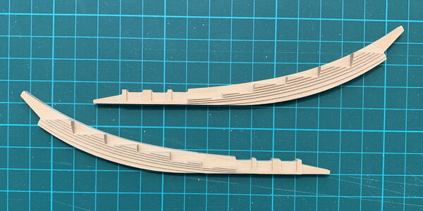
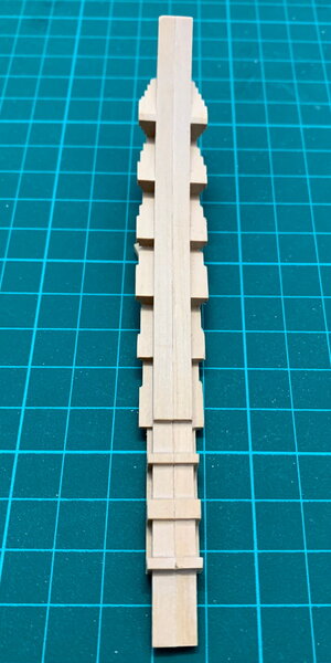
The next picture shows both halves after finishing the milling process. The small steps are only a help to minimize the grinding.
Fly-021.jpg
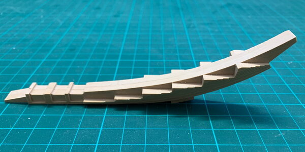
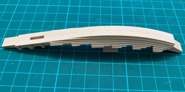
The last three pictures show the finished deadwood. I am not really happy with the result. Small spots are chipped in two places. I am afraid that the milling cutter was no longer sharp enough. I've had this problem several times in the last two months but haven't found a way to determine when it's time to change a milling cutter.
Fly-023.jpg

Fly-024.jpg

Fly-022.jpg
 
I have not much to show, but made a lot of progress in the last four weeks. Today I finished the reconstruction of the frames:
  • 55 parallel frames
  • 12 fore cant frames
  • 14 after cant frames.
For the thickness of the frames I used the information from Steel "Elements and Practice of Naval Architecture" and the the "Shipbuilders repository".

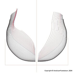
The picture shows the control drawing of the inner edge of the frames.

Fly-025.jpg

The after side is looking a bit strange. But this is correct because I have drawn every cant frame with the correct projection plane.
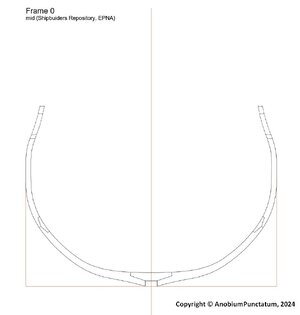
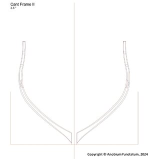
Also I have calculated and drawn the positions of the different chocks. The last two pictures show the completed mid ship frame and one of the cant frames.

Fly-026.jpg Fly-027.jpg

From these drawings I will now prepare the part-drawings for my CNC. After finishing these drawings I have a lot to build for the next few months.
 
I have not much to show, but made a lot of progress in the last four weeks. Today I finished the reconstruction of the frames:
  • 55 parallel frames
  • 12 fore cant frames
  • 14 after cant frames.
For the thickness of the frames I used the information from Steel "Elements and Practice of Naval Architecture" and the the "Shipbuilders repository".

The picture shows the control drawing of the inner edge of the frames.

View attachment 441623

The after side is looking a bit strange. But this is correct because I have drawn every cant frame with the correct projection plane.
Also I have calculated and drawn the positions of the different chocks. The last two pictures show the completed mid ship frame and one of the cant frames.

View attachment 441624 View attachment 441625

From these drawings I will now prepare the part-drawings for my CNC. After finishing these drawings I have a lot to build for the next few months.
Nice to see the progress of your drawings, Christian.
Regards, Peter
 
Back
Top