De Zeven Provincien 1665 - 1.100, Fa. Seahorse (Tomasz Weremko)

Joined
Nov 9, 2018
Messages
231
Points
253

Location
Berlin, Germany
Ahoy everyone,
A year ago, my then sweetheart gave me the kit for the Zeven Provincien for my birthday. I looked longingly at the box from time to time, but was disciplined enough to continue building my Columbus fleet. But when I had finished the Pinta, my discipline came to an end. Besides, the next birthday was approaching, and how could I hope for new presents when I hadn't yet touched the present from the previous year? ROTF

And so several great things happened last month:
On March 5, I started building the Zeven Provincien.
On March 15, I married my sweetheart.
On March 17, it was my birthday again and I received presents again.

That's just a bit of background history to amuse everyone. :cool:

I don't need to present the kit here; the designer himself has shared his test build with us here. (Of course, that sets the standard for me now - oh dear, I hope I don't embarrass myself too much...:eek:)
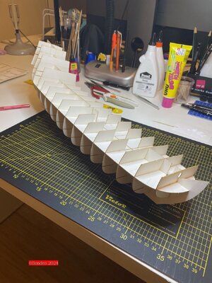
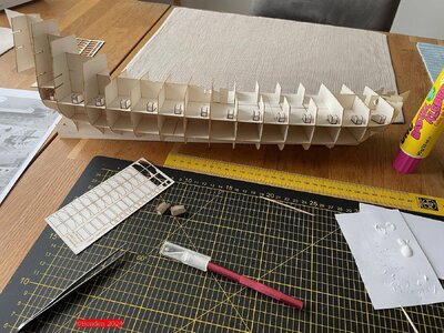
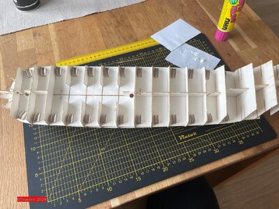
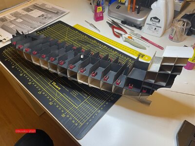
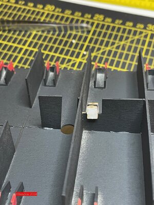
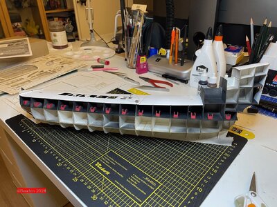
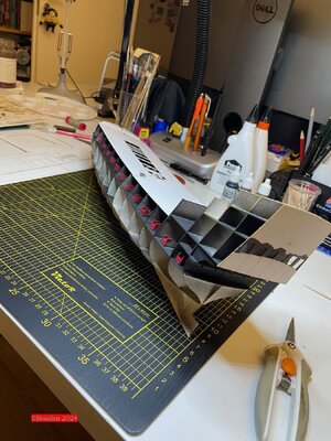
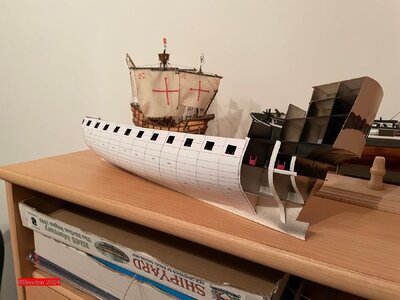
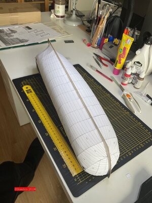
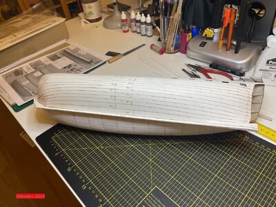
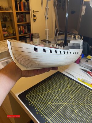
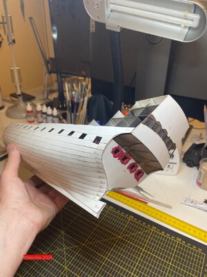
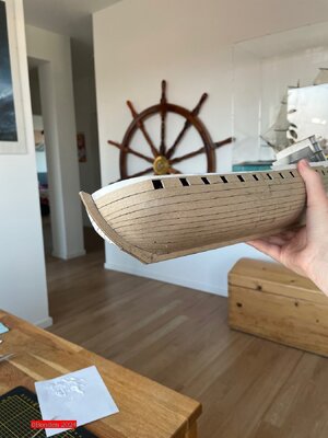
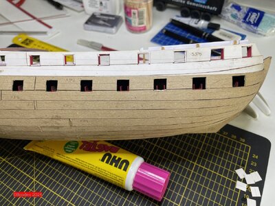
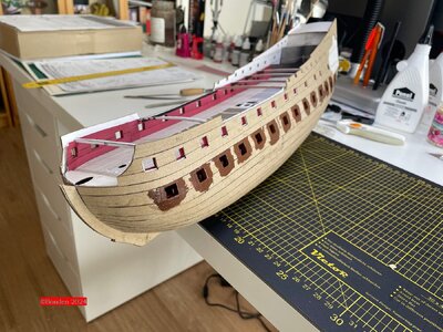
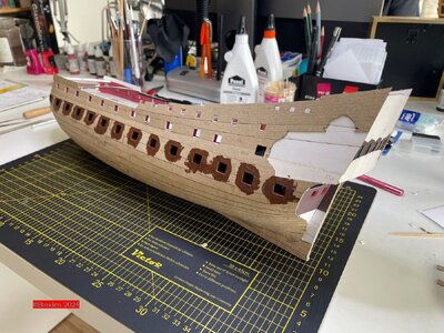
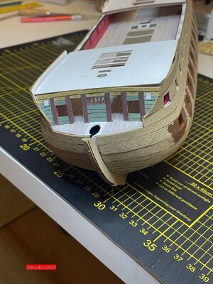
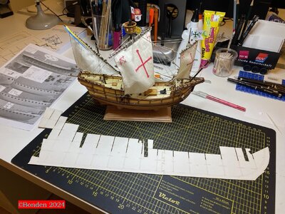
The construction of the ship progressed quite quickly at the beginning. This was mainly due to the fact that I got the complete package, i.e. all the lasercuts. This meant that the frame was finished quickly. For the "zero" planking, I glued narrow, thin strips of paper to the edges of the frames - this made it much easier to attach the vertical parts.
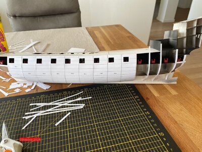
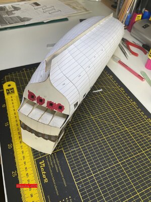
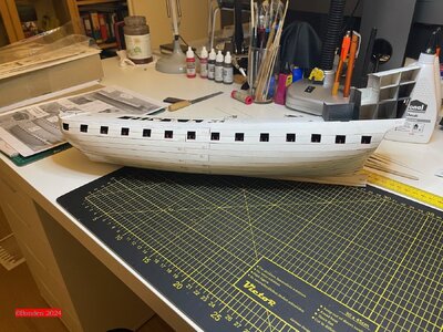
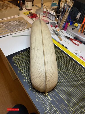
The first and second planking of the fuselage then also went well.
ZP019.jpgZP020.jpgZP022.jpgZP023.jpgZP024.jpgZP025.jpgZP026.jpgZP028.jpgZP030.jpgZP031.jpgZP032.jpgZP033.jpgZP036.jpgZP037.jpgZP038.jpgZP039.jpgZP042.jpgZP044.jpg

We'll continue in a moment.
 
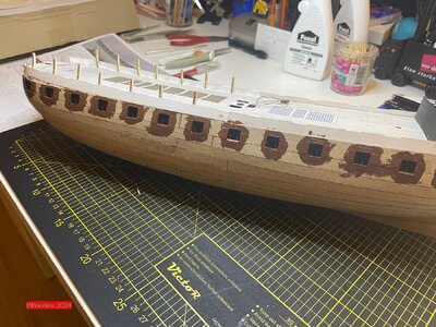
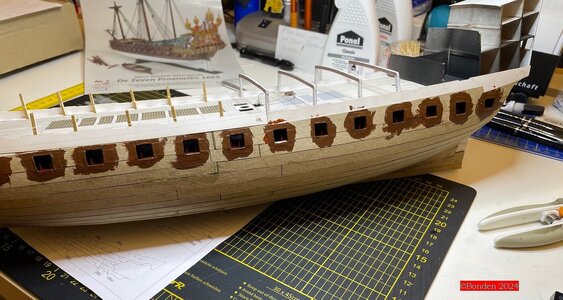
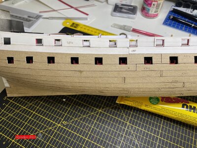
You can see in the pictures of the first planking where the hull does not yet look nice. I sanded these areas a little and then fitted the second planking. And I'm totally thrilled with it! Such a beautiful hull, I really only have to sand very little before the final planking.

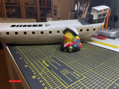
I had a visitor at the shipyard today - and I'm afraid I won't be able to get rid of him. Says he's the one I'm building this ship for and I should get a move on and everything. Now he's constantly interrupting. I haven't had a demolition yet - maybe I'll take the first deck plate off again and see if there's room for this annoying colleague...
ZP043.jpg
ROTF

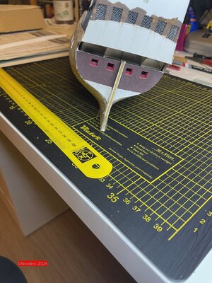
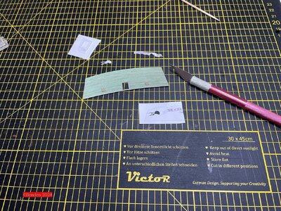
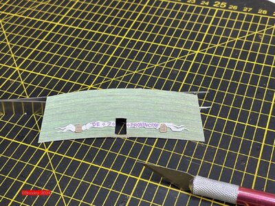
I've already done a bit of work on the rear and prepared a part that I'll attach later. Cutting out the lettering with the name of the ship was a nice finger exercise.
ZP050.jpg
ZP047.jpg


ZP048.jpg

I have a confession to make: I made a big mistake and completely forgot to fit the pedestal frames in time. I then found an elegant solution to make up for it, but I won't need it. I want to show the ship "underway" and not just before a battle or at a naval parade. This means that all the cannons are retracted and all the ports are closed. The cannon telegraphing will certainly be exciting, but I'm looking forward to it.
ZP052.jpg

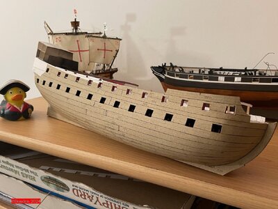
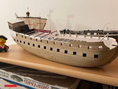
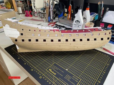
This is the current status.

ZP054.jpg

@0Seahorse
Dear Tomek, we are happy to exchange ideas here now. I'm sure it's also interesting for you to hear what experiences a "customer" has had with your product. I would be delighted if you would accompany my construction here.

Best regards

Bonden
 
@0Seahorse
Hello Tomek,
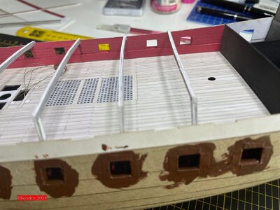
I am at a bit of a loss. I fitted the inner railing of the main deck on the starboard side. But in the aft area, the inner and outer openings don't match. From the middle it is correct. Up to this point, I have worked almost without exception with the laser-cut parts, only parts 52 were cut out by hand. But I can't see that I've made a mistake there; the photo of the inside of the deck shows that everything is OK.
Well, it's not all that bad, because I decided to keep all the piece ports closed and show the ship "underway". Nevertheless, I wonder where the fault lies? I will have the same problem on the port side, I have already stopped the parts there for a test.
ZP055.jpgZP056.jpgZP057.jpg
 
Hi Bonden,
Sorry I didn't reply earlier, but I had stomach problems. All your comments as a customer are very important to me, any ideas and observations may be very useful to me in the future. So go ahead!
@Ben@ Thank you for valuing my work so highly.
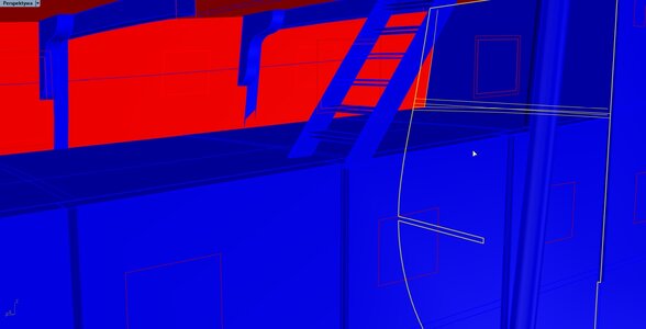
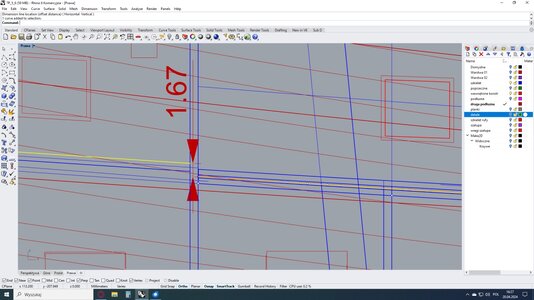
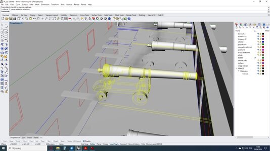
As for the gunports you're having trouble with, I was wondering (with my stomach hurting) about the cause. If this difference is 1.67 mm, it would mean that you glued the deck too high because you used the marking on frame 14, which is towards the stern. In other words, you "rotated" frame 14. In the screenshot below you have two markings: the bent one refers to the deck, and the straight one refers to the horizontal reinforcement at the back (from the stern side). At the side itself, the difference in height is, according to the design, 1.67 mm.
Bonden.jpg
Bonden 2.jpg
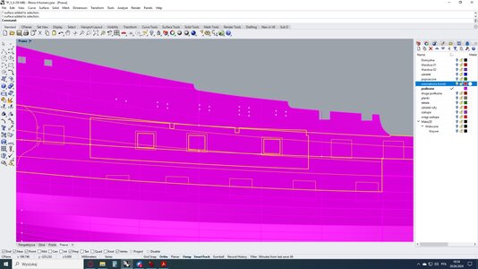
Notice the third screenshot and the relative positioning of the two parts that do not match: at the front the inner part is above the cover, at the back it is below.
Bonden 3.jpg
Of course, it may be that you were not mistaken and there is some error on my side. So far, no one has brought this to my attention to this problem.
If the inner part of the sideboard is not glued in yet, you can cut it from the bottom after fitting. Fortunately, this place is not visible in the model.

Greetings
Tomek
 
Hello Tomek,

Thank you for your reply. Contrary to my fears, I didn't have the problem on the port side. And as the following pictures show, everything else fits perfectly. The symmetry is also right, no matter which side I look at critically. So I don't know why it doesn't fit in one corner. Well, it doesn't matter, once I have the end planking on and the piece ports are closed, you can no longer see the little dilemma.
With the last parts of the first and second planking, the outer framework is now complete - I'll put the final, printed parts on later.
ZP064.jpgZP065.jpgZP066.jpg
And, dear Tomek, I'm already announcing the next questions... ;)

@all: Thx for the nice comments!

Greatings

Bonden
 
@0Seahorse
Hello Tomek,

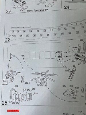
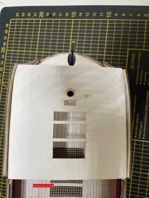
here is the next question as announced. I'll start now with the parts that go on the main deck. I'm wondering about the nail bench with the parts 60 a - j. According to the construction drawing, this should be placed directly in front of the foremast. But when the forecastle deck is on, this nailing bench has no function, you can't put a rope there. (I have only loosely laid the deck part 107 for the photo, not yet glued it down). And another question about the servant (part 61a-d) behind the foremast: Is the halyard for the foremast attached here, similar to the one for the main mast? In later pictures you can see that there is a structure peeking out of the forecastle deck, but the building instructions don't show this anywhere, or I haven't found it.
ZP069.jpgZP067.jpgZP068.jpg

I hope I'm not annoying you too much with my questions.

Best regards

Bonden
 
Hello Tomek,

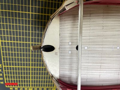
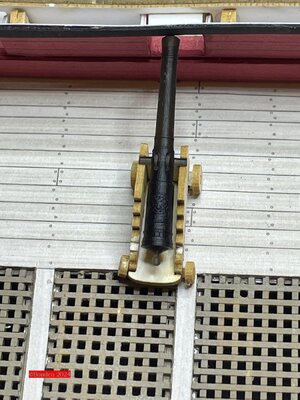
unfortunately I still have a problem: Could it be that your gun barrels are too long? I have now finished the first gun carriage for an 18-pounder and added a gun barrel from your 3D range. If I now want to set it up in "ship in motion" mode, the rear wheels of the gun carriage stand on the grating. That doesn't seem right to me. The barrel measures 30 mm without the pommel, with 32 mm. I have leafed through my books and can find tube lengths of 7.5 to max. 8 feet for 18-pounders from this period in several places, which corresponds to 2.29 to 2.44 m.
ZP070.jpg
Best regards
Bonden
 
Hi Bonden,
I spent some time looking for tips and answers to your questions.
Let's start with the easiest one. Yes, parts 61a-d are halyard mounts for foremast as for mainmast. This is written in point 16 of the instructions.

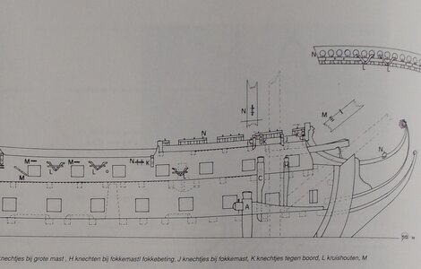
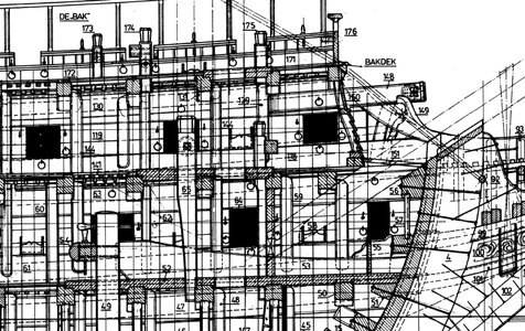
Parts 60a-j - this component is visible on all the plans I have or have seen.
fok betting.jpg
C.G.Dik

fok betting 2.jpg
fok betting 3.jpg
O. Blom

I'm not sure, but I remember in the recesses of my brain (or I just dreamed it :) that I saw a drawing in which some ropes went directly through holes in the "bakdek" at this point (so most likely to component 60a-j). Unfortunately, I couldn't find this drawing. Due to the fact that fastening these ropes on the model under the deck is basically impossible, I skipped the search, especially since all the ropes were placed in accessible places on the decks. If anyone knows more about what the use of this fife rail/bitts was, maybe they can clear up our doubts. I remember that Ab Hoving wrote to me that this type of "devices" were made "in stock" so that they could be used for other tasks if necessary.
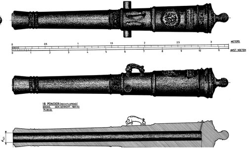
And artillery. I used Blom's drawings, where the 18-pounder is over 11 Amsterdam feet, or approximately 3.30 meters. I definitely don't feel like correcting Mr. O. Blom, so I took it for granted.
18 pounder.jpg
O. Blom

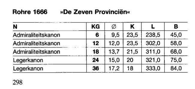
In a book by Modfeld (and others) titled "Schiffsgeschutze 1350 bis 1870" I found this:
modfeld De7Prov.jpg
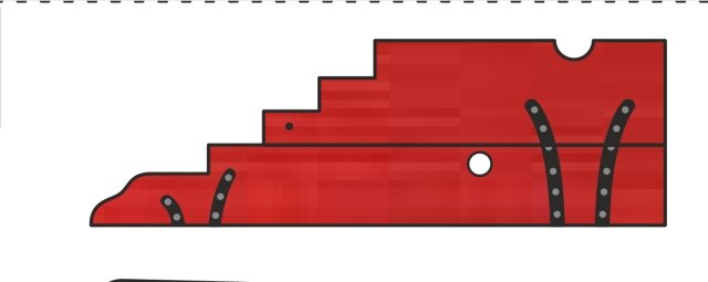
I can't see it in the photo, but it seems to me that you glued the rear axle too far back, i.e. on the last rounded "step", and it should be glued on the first "perpendicular" step, perhaps it is enough to move the rear axle of the gun carriage by 2-3 mm forward.
laweta.jpg
In the design, the rear wheel is on the edge of grating.
gun cofnięty.jpg
Greetings
Tomek
 
.​

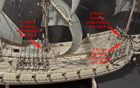
Bonden, please find the solution to your problem in the photo below of a ship model made in 1654.

As for the length of the cannon barrels, you can easily get them to your liking by replacing the bronze gun barrels with shorter cast iron ones (and shortening the carriages accordingly). No more than a small surgery is required.


Norske Løve 1654.jpg

.​
 
Hello Tomek,

Thank you very much for the quick and comprehensive answers. That helps me a lot. I will follow the advice about moving the rear axle. Then I won't have to worry about the heavy gun crashing through the thin grating at some point. :) The photo of the old model is very interesting; I've never seen openings like that before. From a purely practical point of view, it would certainly be better to leave a slightly larger opening instead of these holes. That would make it easier for the sailors to change buoys there when repairs are needed, to attach new blocks, etc. But sailors have always been resourceful guys - they've always found simple, pragmatic solutions.
And finally, one last word on the length of the cannons: I had looked in Hoeckel's book on model building of 16th and 17th century ships, among others, and as a comparison in Blake/Lavery Nelson's Navy (to compare how it was 100 years later). However, I will do as you do and not question the statements of Blom and Mondfeld.

Sorry again if I am annoying with my questions, but people who ask can be helped, and you have helped me very well. Thank you again!

Best regards

Bonden
 
Back
Top