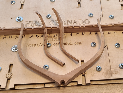
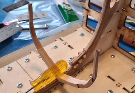
CAF Granado 1/48 PoF Bomb Vessel by Signet

Joined
Nov 17, 2021
Messages
857
Points
318

Location
Columbia, SC
There are quite a number of excellent CAF Granado builds posted here (thank goodness for all the insight and help they are providing me), but for my assistance much more than yours, I am posting this build log, trying my hand at this excellent kit and will post the good and the bad here. I'm just a bit concerned that this is above my skill level, but hope that if I treat each small frame and part as its own model, I will eventually complete it. I know a number of others have quit building this kit (surprisingly to me, mostly after completion of Part 1, the main hull outer structure, which I think is the most difficult part), but sincerely hope that will not be the case here, health or other unavoidable issues notwithstanding.

There is no need for me to take photos or talk about opening the kit (I got all 3 parts at once), as Uwe and others have covered that so well. (Thank goodness they do this, because it is so very helpful when deciding what kit to build next.) I will at least show my progress, and where what I do deviates from the norm, as it often does, I will show that along with the result, good or bad. I know upfront I will not be splitting the hull horizontally like Uwe, but hope to provide some visibility of the inside structure and details through cut-out portions of the hull and deck.

Since most all my photos have been, and will be, photographed in my den "workplace", I thought I'd show a couple photos of my den "BG" (Before Granado):
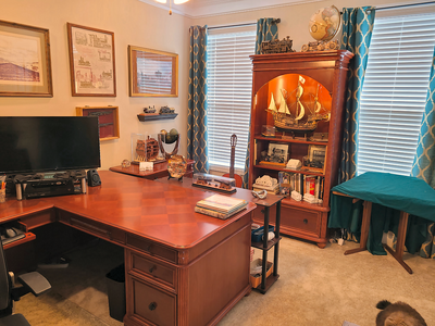
1714153344589.png
Yes, that's the back and tail of one of our cats at the lower right.
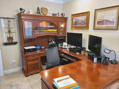
1714153392597.png
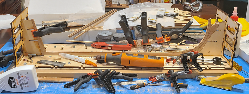
My den obviously serves as my computer room, study, TV room and more, in addition to my hobby room and ship model construction room. It isn't suited well to building models, as I love the furniture and want to protect it, but that's what I have. I also have a corner of the garage with all my power tools in, but that is not as comfortable a place to do fine work and assembly, so that will be done here. The lights atop either end of the hutch help provide light from the back while working, in addition to the ceiling and spot lights.

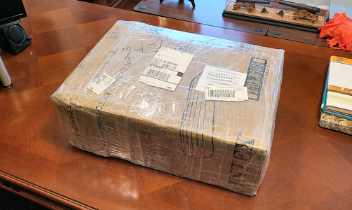
On to the kit! I ordered it from CAF on March 28, and received it this past Wednesday, April 24, taking longer than usual. I think I hit upon a few snags in the process, like ordering late Thursday, a weekend, then a Chinese holiday, and then UPS decided to lose the package, or at least delay it I guess, rather than lose it. That wasn't a problem - I was required by the Admiral to clean up both my den and the garage before starting any new project anyhow. But eventually, it made it here, in one 18 pound box:
1714153717301.png
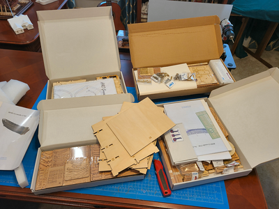
Certainly well packed and protected (even against the kind of rain that soaked my MarisStella Ragusian Carrack when it was delivered, but no rain this time). And naturally, the insides is what I was most interested in:
1714153803334.png
Unlike Keith and some others, I do not like unopened boxes. While I didn't tear everything apart to make an inventory (suspecting I'd lose more by doing so than doing it later), I did open each box, look at the excellent drawings (less than I expected, but understandable given the excellent 3D diagrams in the instruction booklets) and the included parts. A couple packs had broken open (the brass mortar balls seem to break in most packs I've seen). The mortar and cannon pack also was broken, with barrels strewn around, but I think I got all the mortar pieces including the capslocks. And I'm sure Tom at CAF will help if I end up missing something down the road.

The first thing I did was rough-assemble the keel, and place it on the bedplate of the assembly cradle:
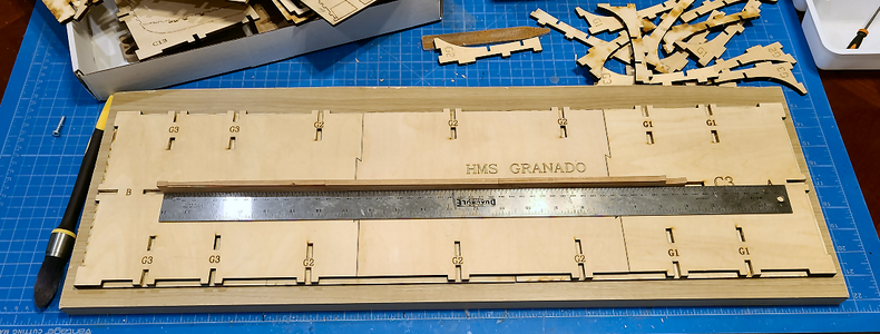
1714154074775.png
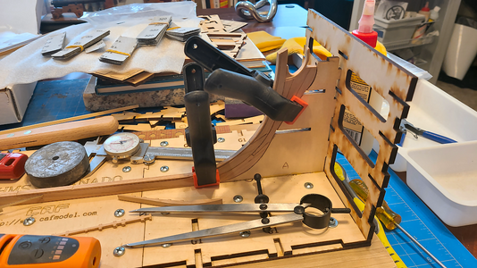
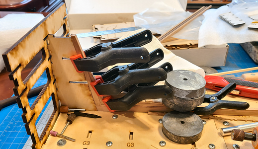
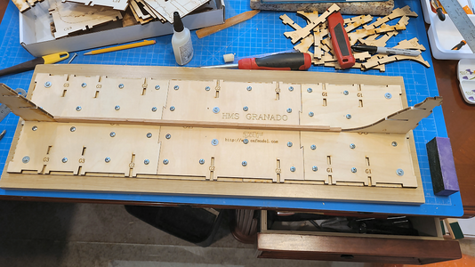
I hadn't thought I needed the thick bottom plank for support, because the entire cage ends up so rigid, but Uwe and Keith convinced me to add it, and I had an extra shelf from my kitchen that I decided to use. I realize now that I will not be completely building the cage before actually using portions of it, so attaching it securely to the base was a good idea:
1714154189602.png
I followed Uwe's and Keith's normal method of "overkill" in attaching it to the base. It's not going anywhere. And I figure that during construction I can place the entire kit and structure on end, on the floor, to make room for other work.

I will be starting out rather slowly on this. For example, I want to use the stem and stern supports of the cage to locate the pieces, rather than just the plans, assuming they will locate and support the pieces throughout the build, so matching them is most important. CAF also shows dry fitting all the frames to the keel before going further with the cage than I show above.

So, I already have questions:
The basic keel is made up of 3 parts, with a tab of each fitting into the slot of the base of the cage:
1714154357033.png
Aha - I see I have gotten all the way to Step 1 before asking my first question! Cautious Anyhow, unless the future mounting base has similar slots for these 3 tabs to fit into, which is doubtful, they will have to be removed later. These tabs are 6mm thick, and can just see myself holding a completed and painted model on my lap, trying to carve or cut them away without dropping the model or ruining the finish. Might it be a good idea to cut a groove on each side of the tab as a working line to facilitate later removal? They'd still be strong enough to locate the keel, and once framing starts, they and the stern and stem pieces will hold it as well. Or do you have other suggestions for doing this?

Oh, and not that it matters for the build, but I have rarely seen the Granado referred to as "HMS Granado", despite being a ship in His Majesty's navy. Peter Goodwin's book just refers to it on the title as "The Bomb Vessel Granado", and most text just says "The Granado". As I said, very rarely has it been referred to as HMS Granado, a couple have referenced it as "H.M.B.V. Granado", for His Magesty's Bomb Vessel", but I was just wondering about this. Perhaps since it served a dual purpose, as both a sloop and a bomb vessel?

That's it for today. I hope you will decide to join me on this journey, so I can ask more questions, receive more information and guidance, and in general benefit from all of your experience in my build.
 
Hello Signat, it's great that you dared to do it. I'm already looking forward to your build and will be delighted to be there.
 
The more the merrier! Always room for all!
Thanks very much for the encouragement. I think I will need it (already screwed up a bit).
I'll pull up a chair next to Tobias. Good luck with this challenging build!
Paul, didn't I read that you were building this model too? I looked for a build log, but couldn't find it.
 
The more the merrier! Always room for all!
Thanks very much for the encouragement. I think I will need it (already screwed up a bit).

Paul, didn't I read that you were building this model too? I looked for a build log, but couldn't find it.
Nope. I opted for another POF build. You can use the link in my 'signature.'
 
There are quite a number of excellent CAF Granado builds posted here (thank goodness for all the insight and help they are providing me), but for my assistance much more than yours, I am posting this build log, trying my hand at this excellent kit and will post the good and the bad here. I'm just a bit concerned that this is above my skill level, but hope that if I treat each small frame and part as its own model, I will eventually complete it. I know a number of others have quit building this kit (surprisingly to me, mostly after completion of Part 1, the main hull outer structure, which I think is the most difficult part), but sincerely hope that will not be the case here, health or other unavoidable issues notwithstanding.

There is no need for me to take photos or talk about opening the kit (I got all 3 parts at once), as Uwe and others have covered that so well. (Thank goodness they do this, because it is so very helpful when deciding what kit to build next.) I will at least show my progress, and where what I do deviates from the norm, as it often does, I will show that along with the result, good or bad. I know upfront I will not be splitting the hull horizontally like Uwe, but hope to provide some visibility of the inside structure and details through cut-out portions of the hull and deck.

Since most all my photos have been, and will be, photographed in my den "workplace", I thought I'd show a couple photos of my den "BG" (Before Granado):
View attachment 443913
Yes, that's the back and tail of one of our cats at the lower right.
View attachment 443914
My den obviously serves as my computer room, study, TV room and more, in addition to my hobby room and ship model construction room. It isn't suited well to building models, as I love the furniture and want to protect it, but that's what I have. I also have a corner of the garage with all my power tools in, but that is not as comfortable a place to do fine work and assembly, so that will be done here. The lights atop either end of the hutch help provide light from the back while working, in addition to the ceiling and spot lights.

On to the kit! I ordered it from CAF on March 28, and received it this past Wednesday, April 24, taking longer than usual. I think I hit upon a few snags in the process, like ordering late Thursday, a weekend, then a Chinese holiday, and then UPS decided to lose the package, or at least delay it I guess, rather than lose it. That wasn't a problem - I was required by the Admiral to clean up both my den and the garage before starting any new project anyhow. But eventually, it made it here, in one 18 pound box:
View attachment 443915
Certainly well packed and protected (even against the kind of rain that soaked my MarisStella Ragusian Carrack when it was delivered, but no rain this time). And naturally, the insides is what I was most interested in:
View attachment 443916
Unlike Keith and some others, I do not like unopened boxes. While I didn't tear everything apart to make an inventory (suspecting I'd lose more by doing so than doing it later), I did open each box, look at the excellent drawings (less than I expected, but understandable given the excellent 3D diagrams in the instruction booklets) and the included parts. A couple packs had broken open (the brass mortar balls seem to break in most packs I've seen). The mortar and cannon pack also was broken, with barrels strewn around, but I think I got all the mortar pieces including the capslocks. And I'm sure Tom at CAF will help if I end up missing something down the road.

The first thing I did was rough-assemble the keel, and place it on the bedplate of the assembly cradle:
View attachment 443917
I hadn't thought I needed the thick bottom plank for support, because the entire cage ends up so rigid, but Uwe and Keith convinced me to add it, and I had an extra shelf from my kitchen that I decided to use. I realize now that I will not be completely building the cage before actually using portions of it, so attaching it securely to the base was a good idea:
View attachment 443918
I followed Uwe's and Keith's normal method of "overkill" in attaching it to the base. It's not going anywhere. And I figure that during construction I can place the entire kit and structure on end, on the floor, to make room for other work.

I will be starting out rather slowly on this. For example, I want to use the stem and stern supports of the cage to locate the pieces, rather than just the plans, assuming they will locate and support the pieces throughout the build, so matching them is most important. CAF also shows dry fitting all the frames to the keel before going further with the cage than I show above.

So, I already have questions:
The basic keel is made up of 3 parts, with a tab of each fitting into the slot of the base of the cage:
View attachment 443919
Aha - I see I have gotten all the way to Step 1 before asking my first question! Cautious Anyhow, unless the future mounting base has similar slots for these 3 tabs to fit into, which is doubtful, they will have to be removed later. These tabs are 6mm thick, and can just see myself holding a completed and painted model on my lap, trying to carve or cut them away without dropping the model or ruining the finish. Might it be a good idea to cut a groove on each side of the tab as a working line to facilitate later removal? They'd still be strong enough to locate the keel, and once framing starts, they and the stern and stem pieces will hold it as well. Or do you have other suggestions for doing this?

Oh, and not that it matters for the build, but I have rarely seen the Granado referred to as "HMS Granado", despite being a ship in His Majesty's navy. Peter Goodwin's book just refers to it on the title as "The Bomb Vessel Granado", and most text just says "The Granado". As I said, very rarely has it been referred to as HMS Granado, a couple have referenced it as "H.M.B.V. Granado", for His Magesty's Bomb Vessel", but I was just wondering about this. Perhaps since it served a dual purpose, as both a sloop and a bomb vessel?

That's it for today. I hope you will decide to join me on this journey, so I can ask more questions, receive more information and guidance, and in general benefit from all of your experience in my build.
Good morning. Beautiful study/den/shipyard. My chair is up in the front row. Enjoy! Cheers Grant
 
Great start on the build, and good luck with keeping the workspace this clean.

I like your displays, especially the OcCre trains above the desk.

With all the Granado, full and cross sections builds, maybe time to set up a group to locate them all easier.
 
Great start on the build, and good luck with keeping the workspace this clean.
Yeah, that's what I tell my wife, but she doesn't always listen.
I like your displays, especially the OcCre trains above the desk.
Thanks, it worked out well.
With all the Granado, full and cross sections builds, maybe time to set up a group to locate them all easier.
Yeah, I could take over the next lower shelf in the bookcase, but that wouldn't be a great place, I think. I intend to completely plank and finish one side of the Granado, and leave the structure and some of the innards visible on the other, so it would be best in a separate case, probably on my desk or something. My wife is not as nautically-minded (despite being the Admiral), so I'm afraid all my constructions except clocks and music boxes are confined to my den.
 
There are quite a number of excellent CAF Granado builds posted here (thank goodness for all the insight and help they are providing me), but for my assistance much more than yours, I am posting this build log, trying my hand at this excellent kit and will post the good and the bad here. I'm just a bit concerned that this is above my skill level, but hope that if I treat each small frame and part as its own model, I will eventually complete it. I know a number of others have quit building this kit (surprisingly to me, mostly after completion of Part 1, the main hull outer structure, which I think is the most difficult part), but sincerely hope that will not be the case here, health or other unavoidable issues notwithstanding.

There is no need for me to take photos or talk about opening the kit (I got all 3 parts at once), as Uwe and others have covered that so well. (Thank goodness they do this, because it is so very helpful when deciding what kit to build next.) I will at least show my progress, and where what I do deviates from the norm, as it often does, I will show that along with the result, good or bad. I know upfront I will not be splitting the hull horizontally like Uwe, but hope to provide some visibility of the inside structure and details through cut-out portions of the hull and deck.

Since most all my photos have been, and will be, photographed in my den "workplace", I thought I'd show a couple photos of my den "BG" (Before Granado):
View attachment 443913
Yes, that's the back and tail of one of our cats at the lower right.
View attachment 443914
My den obviously serves as my computer room, study, TV room and more, in addition to my hobby room and ship model construction room. It isn't suited well to building models, as I love the furniture and want to protect it, but that's what I have. I also have a corner of the garage with all my power tools in, but that is not as comfortable a place to do fine work and assembly, so that will be done here. The lights atop either end of the hutch help provide light from the back while working, in addition to the ceiling and spot lights.

On to the kit! I ordered it from CAF on March 28, and received it this past Wednesday, April 24, taking longer than usual. I think I hit upon a few snags in the process, like ordering late Thursday, a weekend, then a Chinese holiday, and then UPS decided to lose the package, or at least delay it I guess, rather than lose it. That wasn't a problem - I was required by the Admiral to clean up both my den and the garage before starting any new project anyhow. But eventually, it made it here, in one 18 pound box:
View attachment 443915
Certainly well packed and protected (even against the kind of rain that soaked my MarisStella Ragusian Carrack when it was delivered, but no rain this time). And naturally, the insides is what I was most interested in:
View attachment 443916
Unlike Keith and some others, I do not like unopened boxes. While I didn't tear everything apart to make an inventory (suspecting I'd lose more by doing so than doing it later), I did open each box, look at the excellent drawings (less than I expected, but understandable given the excellent 3D diagrams in the instruction booklets) and the included parts. A couple packs had broken open (the brass mortar balls seem to break in most packs I've seen). The mortar and cannon pack also was broken, with barrels strewn around, but I think I got all the mortar pieces including the capslocks. And I'm sure Tom at CAF will help if I end up missing something down the road.

The first thing I did was rough-assemble the keel, and place it on the bedplate of the assembly cradle:
View attachment 443917
I hadn't thought I needed the thick bottom plank for support, because the entire cage ends up so rigid, but Uwe and Keith convinced me to add it, and I had an extra shelf from my kitchen that I decided to use. I realize now that I will not be completely building the cage before actually using portions of it, so attaching it securely to the base was a good idea:
View attachment 443918
I followed Uwe's and Keith's normal method of "overkill" in attaching it to the base. It's not going anywhere. And I figure that during construction I can place the entire kit and structure on end, on the floor, to make room for other work.

I will be starting out rather slowly on this. For example, I want to use the stem and stern supports of the cage to locate the pieces, rather than just the plans, assuming they will locate and support the pieces throughout the build, so matching them is most important. CAF also shows dry fitting all the frames to the keel before going further with the cage than I show above.

So, I already have questions:
The basic keel is made up of 3 parts, with a tab of each fitting into the slot of the base of the cage:
View attachment 443919
Aha - I see I have gotten all the way to Step 1 before asking my first question! Cautious Anyhow, unless the future mounting base has similar slots for these 3 tabs to fit into, which is doubtful, they will have to be removed later. These tabs are 6mm thick, and can just see myself holding a completed and painted model on my lap, trying to carve or cut them away without dropping the model or ruining the finish. Might it be a good idea to cut a groove on each side of the tab as a working line to facilitate later removal? They'd still be strong enough to locate the keel, and once framing starts, they and the stern and stem pieces will hold it as well. Or do you have other suggestions for doing this?

Oh, and not that it matters for the build, but I have rarely seen the Granado referred to as "HMS Granado", despite being a ship in His Majesty's navy. Peter Goodwin's book just refers to it on the title as "The Bomb Vessel Granado", and most text just says "The Granado". As I said, very rarely has it been referred to as HMS Granado, a couple have referenced it as "H.M.B.V. Granado", for His Magesty's Bomb Vessel", but I was just wondering about this. Perhaps since it served a dual purpose, as both a sloop and a bomb vessel?

That's it for today. I hope you will decide to join me on this journey, so I can ask more questions, receive more information and guidance, and in general benefit from all of your experience in my build.
Hi. So glad your Granado kit arrived safely and that you're documenting your build in this log. Great start and a very good read. I love your beautiful ''den'' but when you start sanding and fairing the frames, a hell of a lot of dust will be created and it's going to get everywhere. Do you intend to do this in your garage workshop? A very interesting point you made about ''HMS'' Granado. I never thought about that. You're right. From now on I shall refer to her as just the Granado. Very best of luck with your build and l shall be following along with great interest and no doubt see how I should have done things better
 
Hi. So glad your Granado kit arrived safely and that you're documenting your build in this log. Great start and a very good read. I love your beautiful ''den'' but when you start sanding and fairing the frames, a hell of a lot of dust will be created and it's going to get everywhere. Do you intend to do this in your garage workshop?
Yes, the frames and such will be sanded in the garage. But I still do hand sanding and more minor Dremel sanding in my den, so yeah, that goes all over. ;-)
A very interesting point you made about ''HMS'' Granado. I never thought about that. You're right. From now on I shall refer to her as just the Granado. Very best of luck with your build and l shall be following along with great interest and no doubt see how I should have done things better
It's great to have you! I'm sure you can help keep me out of trouble.
 
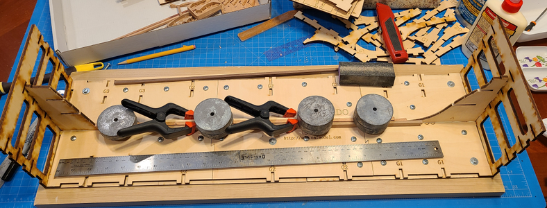
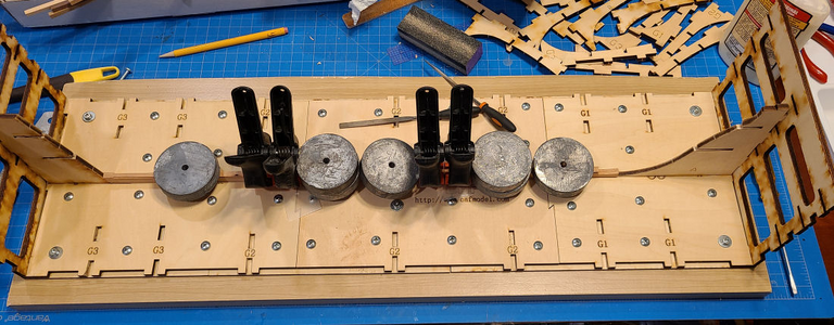
Since the 3-pieces of the main keel fit well, I glued them together.
1714359085248.png
After taking it back up to sand, I realized that it wasn't aligned properly: there was a step in the keel that (obviously) shouldn't have been there. This improperly-focused photo shows the offset or step, worse to the left of the piece:
1714358439522.png
So, my very first gluing of one piece to the other was screwed up. I was more concerned with keeping everything in place and weighted and clamped down, preventing me from checking the alignment. Not the first time I've done that mistake, but I'll be more careful from now on. You also see in the photo above where I've wet down the two joints to take them apart.

After a bit of fine-tuning of the profiles, and being much more careful about the alignment, I glued the 3-piece keel together again:
1714359224789.png
It worked better this time. I've really got to be more careful on this model, as I'm sure it requires really close tolerances. The weights I've used here are extra 1 pound weights from a grandfather clock's weights (I've built 3 of them).

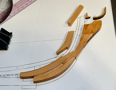
I next took a look at the major pieces of the stem area:
1714359328370.png
Shown prior to any cleanup. The milled pieces require a good bit of cleanup. The laser-cut pieces almost fall out of place, requiring no cutting at all. Of course, I understand and appreciate all the extra work done on the milled pieces - they save a bunch of work and make for more exact shapes.

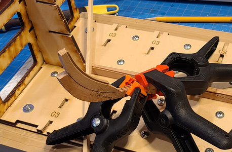
Rather than try to fit all the stem pieces together at once, I worked up from the bottom forward and up, then the next layer added to it, etc. I felt I could insure a good fit in the cage/template, and match the drawing better, by doing one at a time.
1714359559096.png
I checked the fit in the template and against the drawing after each addition. I only sanded the "back" side enough to insure good glue adhesion, usually sanding the piece being added-on to insure a decent fit. Here it is at a later stage with more added parts:
1714359655926.png
The pieces are made well and accurate. Mismatches I've had are caused by too much sanding on my part.

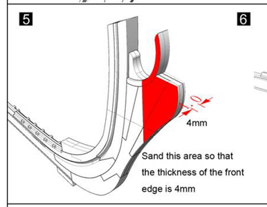
The forward portion of the prow must be tapered somewhat, as shown on the instructions:
1714359800643.png
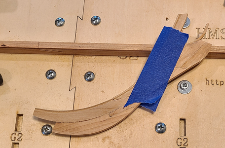
That taper is 1mm in about 20mm, or just under 3 degrees on each side. While I liked the idea of slowly sanding it, so as not to over-sand, I'm notoriously off-kilter on such things, so instead used my trusty belt sander (yeah, that's what I said, a huge, belt sander on a fragile prow of this expensive model). Am I daring, or what? Anyhow, to help, I taped off the area to be sanded:
1714359927193.png
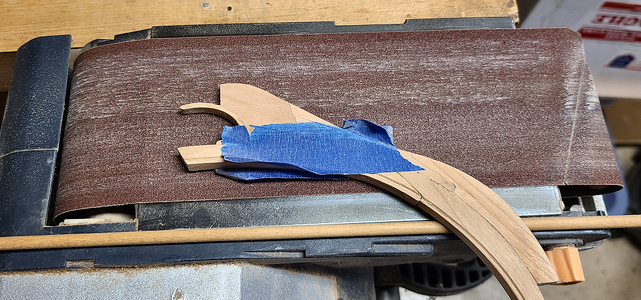
I then used the method below, with my belt sander held in a vise, to sand the profiles:
1714359970820.png
The dowel at the bottom lifted the piece at an angle, which I initially measured with my digital inclinometer, to approach the intended 3 degrees. After I got it close, I just used the tape and the 4mm wide marks on the prow to determine the taper. In the above pic, I've sanded pretty much to the tape, so that's the required angle. This worked out pretty well. Oh, I got out the figurehead of Hermes and confirmed that 4mm wide at that point would give him the wedgie that he needed to sit stably in his final position. I wasn't smart enough to confirm this ahead of time, but did afterwards, thanking CAF for a correct dimension.

The final piece with all of the external pieces mounted in place came out okay:
1714360243718.png
I intentionally added grooves or bevels where pieces go together, to emphasize the main pieces (and hopefully to hide too-wide gaps), which should look good after finishing. The main problem is smoothing those V-ed areas so they aren't rough. Still have a bit to go there.

It fits fairly well into the jig:
1714361263755.png
Any inaccuracies are probably due to my sanding.

Okay, how's CAF doing so far? I'd say really good. The pieces are all accurate and well cut or milled. I do, personally, think it's a shame that they designed the ship to be split at a number of overlapped joints. I have no problem with that where joints would actually occur, but on the above piece, a joint appears across all 4 upper sections. This would never be the case in real life. The first and third pieces, at least, would not be cut there, Possibly more. And it's hard to hide some joints, but not others. Maybe it's better to disguise all of them. But after seeing Uwe's build, I think that most people building this model split horizontally will do as he did - cut a straight line all around. Not try to make over 100 overlapped pieces fit smoothly enough to go together and come apart. And if building split that way, or not doing a split at all, there are a lot more pieces (some of them REALLY tiny) that have to be added, yet really shouldn't exist.
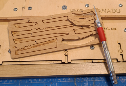
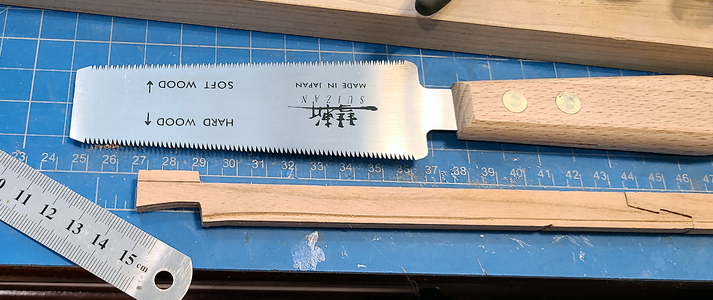
I have already found that the best way to cut out milled pieces is with a small, saw attachment for your razor cutter:
1714360752486.png
The blade is thin enough to not harm the main piece, strong enough to pierce really thin areas, and allows the gap areas to be sawn easily. Laser-cut pieces don't need anything but your fingers and a bit of care where they're very thin.

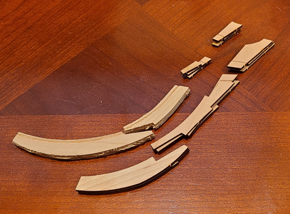
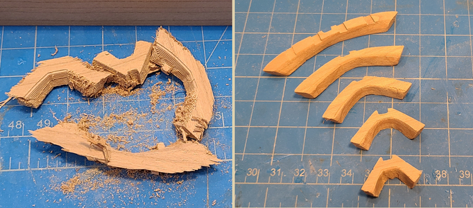
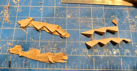
If you haven't worked with milled parts, I'll say that some of them are fairly clean, and obvious, as to the final shape. Others, like the part above, are less so. The portion to the right, as well as the left portion of the piece above it, has a kind of "fringe" that has apparently been caused by the CNC cutter. It seems to depend on the grain - on side will look like the right shape, with slight "steps" caused by the cutter passes, while the other side can have tiny thin pieces still in place (the "fringes" I refer to in the above. It really isn't obvious what the shape should be. And you can't really take a blade and cut it off. You have no idea how deep to cut to remove the fringe but not harm the shape. I've found a good start is to take the end of a needle file, and "scratch" most of the fringe off. Just scraping it with the file parallel to the piece will remove most of the fringe, so you can start to see the piece below it, after which normal blades or sanding can be used.

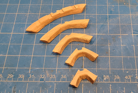
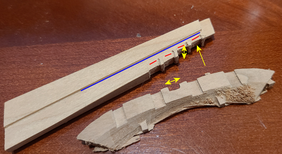
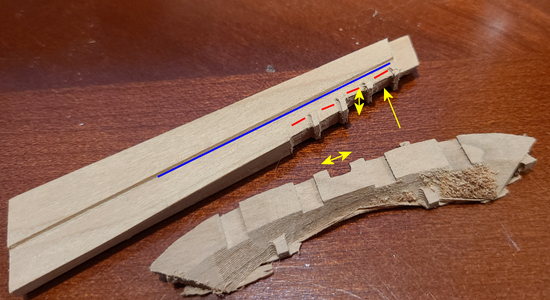
The last part concerning milling is a question, perhaps specific to here, but it's hard to know. Here are photos of the lower left piece above, along with one of the framing pieces that slot into it:
1714361629016.png
1714361651063.png
Basically, the cross pieces have a slot that fits over the end piece, inserting as shown in the arrow, and the double-arrows show the opening and thickness of the piece at that point. The opening is just under 3.5mm. The thickness of the piece it is to slip over, at the areas marked in red, is about 4.5mm. It obviously, won't fit without modification. But behind that is a groove about 3.7mm thick, shown by the straight blue line. So should I increase the groove to fit over the 4.5mm, or shave off the 4.5mm areas to match the groove behind it, and not modify the cross pieces.

I realize this is such a simplistic statement - if something doesn't fit, you just modify one or the other part until it does, right? But the tolerances on this model are all so close, I fear, and exact placement is so important, that I feel it best to ask the question now, rather than just start making changes and live with the possible consequences.
1714362267728.png
BTW, I realized after making these measurements, and examining the other pieces 5L-1 to 5L-4 that also fit into the slots, that I chose the wrong location for the above 5K piece, which should go at the very top. Turns out it was already sized correctly, and now I've made a big groove to fit, so will have to do something to fix that problem. But for the other 4 pieces, as shown in the diagram above, the question still stands. They don't fit, so which to modify?

Thanks for reading and watching, I appreciate it. Obviously, more to follow.
 
I hadn't heard anything back about my question concerning the keel "tabs" that insert into the base of the building jig, so went ahead and put a cut into each at the bottom of the keel, about 1/4 of the keel width in depth, on each side:
1714502583421.png
I assume these will eventually get cut off, so this will give me a good guide of where to cut, and give a good start to that cut. In the meantime, there's enough meat on it to hold the keel into the jig.

It's kind of wild that the 3D milled pieces can end up looking like they should (hopefully):
1714503168651.png
It is a little hard, sometimes, to know exactly what the exact shape of the edges should be. I used a sanding bit on a Dremel on the insides of these, which changed the contour. Hopefully, that's not a problem. Also, I've gone ahead and, in general, widened the grooves in the above pieces, rather than reducing the width of the mating part.

I decided it was about time to glue the stem to the keel. (I'd been avoiding that, because the keel will be come end-heavy once the stem and stern are attached, but hopefully I won't break it.)
1714503370216.png
I'll be keeping everything in this position until most of the deadwood and other material is added above both stem, stern and keel, reinforcing them.

I then glued the end of the stern in place (sorry for all these non-nautical terms):
1714503459147.png
Uwe, and maybe others, will see that I've invested in some Ponal Express glue for most of this kit. I'm pretty happy with it, and only use Titebond Quick & Thick where I have larger gaps to fill.

Then the stern deadwood that helps reinforce that area:
1714503545595.png

And finally the deadwood and such above both ends, as well as the keel add-ons that locate the frames:
1714503573276.png
This will all reinforce the connection of the stem and stern to the keel, hopefully keeping me from breaking it (and, of course, necessary for the model assembly).

As I want this assembly to dry overnight, I made up next the supporting pieces that go on each end for the frames at each end. Here, the stem set is done, while the stern is still in place:
1714503734375.png
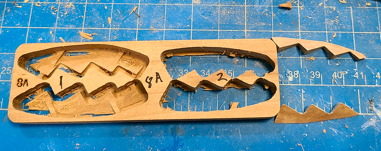
Hard to believe it's possible to get the right pieces out of these. After cutting out with the saw posted above:
1714503788995.png
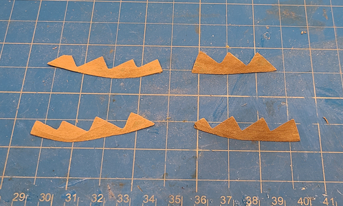
But after shaping, we have something reasonable, albeit thin and a bit fragile):
1714503825470.png
I thought they were about done, but now looking at the photos, I see that I still have sanding to do. My eyes just don't pick up on this.

BTW, I realize, from my posts here at SoS, that a blue cutting board cannot produce a quality model (the reason my Ragusian Carrack does not match Olha's, of course :rolleyes: ). So, I've asked for a new green cutting board for my birthday in a little over a week. I'm sure you will see a huge improvement in my modeling at that time!
 
Well, I said those parts are fragile. I see that the upper-right part in the photo above is missing a step, as it's supposed to be a mirror image of the one below it. It isn't in the block it was cut from, and I see from other photos above it was missing early on. Apparently removed during my over-zealous cleanup process. It is the smallest step, so rather than try to add a piece on, make a new one or ask CAF to supply a new one, I'm going to use it as-is, and just try to mount the frame above in the correct position, then look to see if I need to fill in with something.

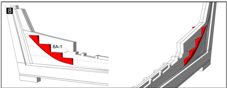
Speaking of those parts, the pair located at the stern (8A-1) are shown located thus:
1714582407582.png
Shown located along a curved line. But that line does not exist on the parts. So I made a copy of this area of the plans side view, cut it out and traced a pencil line to locate the part. I think that will work out.

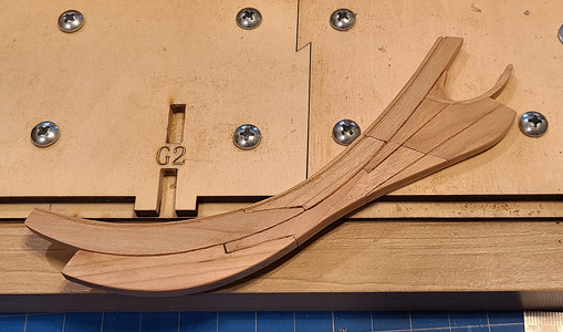
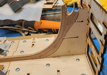
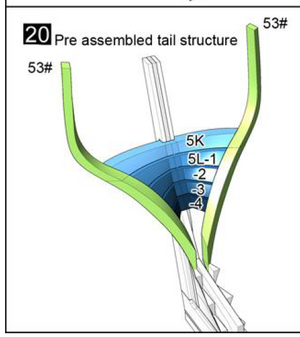
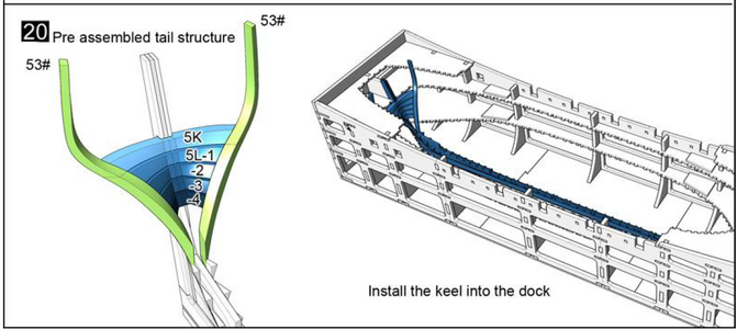
Looking now at the 5 cross pieces that mount on the stern, trying to decide the order to mount parts. I think this is best done before going further with the jig, at least partially:
1714582656227.png
I don't see how I can "Pre assemble" this entire structure and place it in the dock (not jig, as I see in the above, but I may use both). I can see gluing 5K and 5L-1 to -4 in place, then fitting it into the dock, seeing how 53# fits, sanding the assembly and trying again until it fits.
 
I hadn't heard anything back about my question concerning the keel "tabs" that insert into the base of the building jig, so went ahead and put a cut into each at the bottom of the keel, about 1/4 of the keel width in depth, on each side:
View attachment 444892
I assume these will eventually get cut off, so this will give me a good guide of where to cut, and give a good start to that cut. In the meantime, there's enough meat on it to hold the keel into the jig.

It's kind of wild that the 3D milled pieces can end up looking like they should (hopefully):
View attachment 444894
It is a little hard, sometimes, to know exactly what the exact shape of the edges should be. I used a sanding bit on a Dremel on the insides of these, which changed the contour. Hopefully, that's not a problem. Also, I've gone ahead and, in general, widened the grooves in the above pieces, rather than reducing the width of the mating part.

I decided it was about time to glue the stem to the keel. (I'd been avoiding that, because the keel will be come end-heavy once the stem and stern are attached, but hopefully I won't break it.)
View attachment 444901
I'll be keeping everything in this position until most of the deadwood and other material is added above both stem, stern and keel, reinforcing them.

I then glued the end of the stern in place (sorry for all these non-nautical terms):
View attachment 444902
Uwe, and maybe others, will see that I've invested in some Ponal Express glue for most of this kit. I'm pretty happy with it, and only use Titebond Quick & Thick where I have larger gaps to fill.

Then the stern deadwood that helps reinforce that area:
View attachment 444903

And finally the deadwood and such above both ends, as well as the keel add-ons that locate the frames:
View attachment 444904
This will all reinforce the connection of the stem and stern to the keel, hopefully keeping me from breaking it (and, of course, necessary for the model assembly).

As I want this assembly to dry overnight, I made up next the supporting pieces that go on each end for the frames at each end. Here, the stem set is done, while the stern is still in place:
View attachment 444905
Hard to believe it's possible to get the right pieces out of these. After cutting out with the saw posted above:
View attachment 444906
But after shaping, we have something reasonable, albeit thin and a bit fragile):
View attachment 444907
I thought they were about done, but now looking at the photos, I see that I still have sanding to do. My eyes just don't pick up on this.

BTW, I realize, from my posts here at SoS, that a blue cutting board cannot produce a quality model (the reason my Ragusian Carrack does not match Olha's, of course :rolleyes: ). So, I've asked for a new green cutting board for my birthday in a little over a week. I'm sure you will see a huge improvement in my modeling at that time!
Very good work and progress
Ponal Express glue -> Bravo for this decision - I am using it since years
Green cutting mat -> best decision ever -> Your Granado will be the best model
 
Continuing on, here is the completed keel assembly at this point:
1714748419706.png
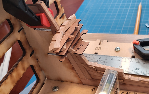
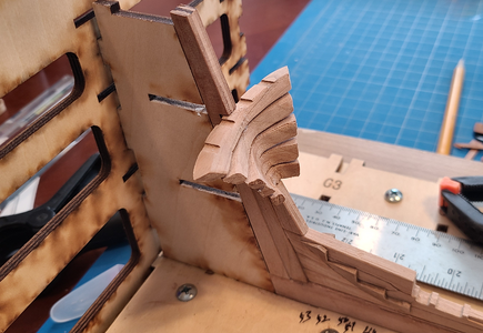
After placing the pieces to the sides of the ends, I went ahead and prepared the crossmembers at the stern:
1714748576093.png
After a bit more finishing, I glued them on to the stern:
1714748617934.png
These pieces have about a 1mm gap between them, so I used scrap pieces of 1mm stock to keep them separate. Not shown, I used a clamp to support the bottom-most piece while it cured, then added the rest.

After the glue was dry, scraps were removed and we have:
1714748726122.png
I then glued together the two pieces of ribs #53, but didn't take a photo of them.

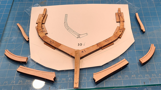
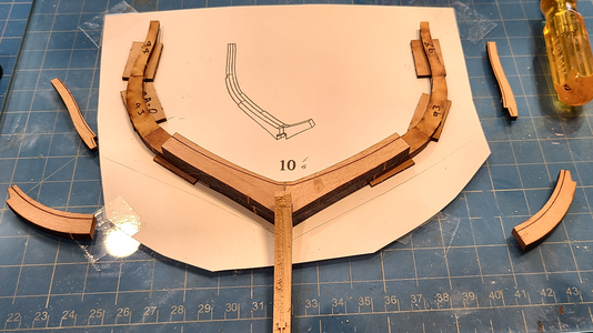
I decided to go ahead and make one of the frames, starting with double frame #10, as outlined in the instructions. To help align the bottom of the frame layers, I used a piece of scrap from the keel wood, which is a good fit to both slots.
1714748922317.png
1714748845603.png
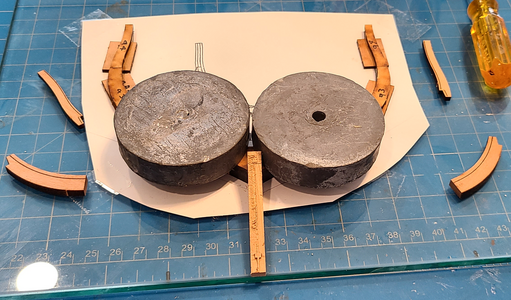
This procedure mostly follows Uwe's procedure, using Fixogum to hold pieces in place and Ponal Express glue (which I'm really starting to love).
1714749001587.png
1714749017942.png

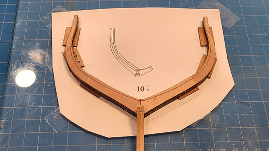
I used a combination of a 1/2" wide hand belt sander, Dremel drum sander and hand sanding on the frame pieces made thus far:
1714749097910.png
And here is frame #10 positioned in place:
1714749152177.png
I'm finding that the frames do not fit over the keel into the depressions milled for them. The openings are not wide enough. Widening the openings is very difficult in these mortised areas, so I sanded the bottom of the frame on each side until it fit. As long as it's centered and it the correct location I don't think the thinner frame at this point will matter.

I'll probably go ahead and make most if not all frames before putting the jig/dock together. That's what the instructions show, testing the frames for fit onto the keel with completely open access is available without the sides of the dock. So I may not post much about that, as it will be a combination of the frames already shown. I figure I may get 1 frame, maybe 2, in a day, so need to get working on them.

Thanks for the comments and all the likes! Until next time!
 
Back
Top