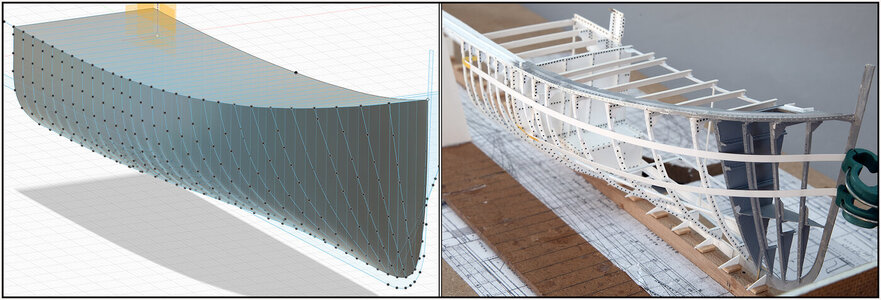
BALDER, Vlaardingen Herring Lugger from 1912, scratch build scale 1:50 Plate-On-Frame

Hi Peter,

It must be great building something which is actually still there. If you have a question about something you just drive over and have a look.
Very nice work enjoy every update.
True story ROTF
Thanks for the compliments, Maarten and Grant.
A visit to the real Balder is always a pleasure. I think I have already a 100+ pictures. Not every detail of the construction can be seen, because a lot is finished with bead parts. (If the grooved planks are indeed called that, like the translation site did).
With the 2 restorations in mind and that the old drawings are not specific to the Balder, I have the necessary AL-FI.
Regards, Peter
 
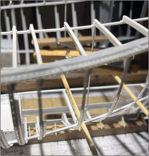
Before making the bilge profile, some preliminary work was done:
0218 Kimweger.jpg
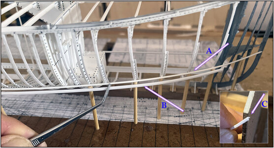
At the start of construction I had placed an Evergreen rod from the front along the bulkheads to the back on both sides. To keep everything stably aligned.
-Installed this rod again, see arrow A. The rod was kept at the correct height with some supports. The sides of the frames followed that rod nicely.
-Then the profile of the bilge could be held outside and bended in the correct shape: running slightly upwards and following the line of the hull, see arrow B.
-Then positioned the profile at the correct angle, see inset with arrow C. The leg must rest on the reverse frames. The arm must be horizontal to place the floor on it later.

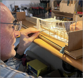
My Admiral couldn't resist taking a photo during fitting and measuring:
0219 Kimweger.jpg
This won't work without tweezers.

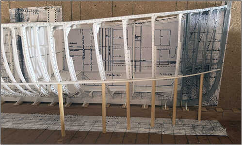
After the necessary fitting and measuring, the bilge scale was secured to the inside of the retaining frames:
0220 Kimweger.jpg
It follows the rod on the outer side neatly.

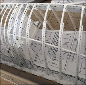
Getting started with the 1st floor beam:
0221 Vloerbalk.jpg
Also a lot of fitting and measuring.
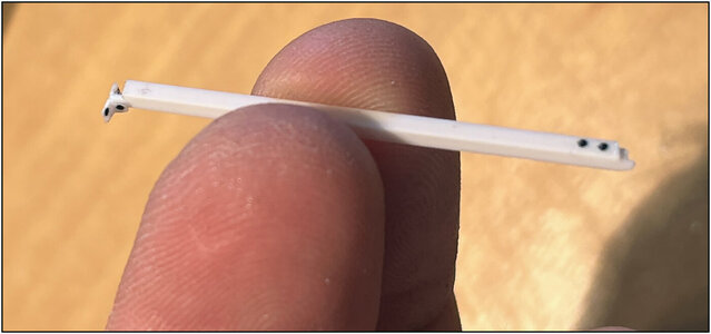
On the left side the end that fits into the profile in the middle of the hull. With 2 'mannetjes' (little pieces of profile).
There is a lip on the inside of the profile on the right side. To strengthen the connection in the bilge profile. The set-up pieces provided with rivets. I don't think I'll be able to reach that anymore.

Set up the starting position for alignment again and align the 1st floor profile along the wooden pin:
0222 Vloerbalk.jpg
The profile sits tension-free between the center and the bilge profile.

Immediately check whether everything is still level:
0223 Vloerbalk.jpg
So the construction mold was tilted again on the construction floor.

Both parts against each other:
0224 Vloerbalk.jpg
Everything still fits and fits together.
Still 11 floor profiles to go.
Regards, Peter
 
Last edited:
amazing and a little bit crazy (in a good way) - the photo made by your admiral is showing us very good, "what" you are doing ......
WOW and once more WOW
Thanks for this nice reaction, Uwe. The Admiral knows how to capture the crucial moments well.
I'm with Uwe...a big WOW! The level of detail is breathtaking (and overwhelming).
Thanks, Paul. I also sat down to take a look at everything.
Tell the Admiral thanks for the picture. It gives a great perspective of how big the Balder is. Great work.

Bill
You also thanks, Bill. When building a model, a reference is sometimes appropriate to show everything in the correct proportion.
Details make the difference
Yep, Stephan. That's what I often quotes: It's all in de details. (How big of small they are.)

Regards, Peter
 
I like how you work, your eyes are on the same level as the model! This gives more precision and accuracy. I always lower the chair when doing milling work. Amazing details, as always.
Thanks, Jim. At this point I had to level the bilge profile exactly with the middle profile of the forecastle floor. Then you can raise you model or lower your seat.
Regards, Peter
 
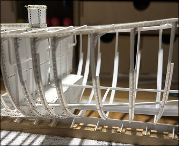
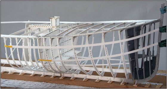
On the Dutch forum a member wondered how I could form a hull from the 'skeleton'.
I wanted to do a check anyway:
0225 Check.jpg
2 strips that will approximately follow the line of the hull plates. Only on the other side, because this side remains open.

It is a bit like the Fushion drawing, the hull plates are pulled over the frames:
0226 Check.jpg
A bit from the same point of view.
Regards, Peter
 
I am wondering:
Is the curvature of the two strips correct? At the bow they should be lower, or?
But I can be completely wrong........
 
I am wondering:
Is the curvature of the two strips correct? At the bow they should be lower, or?
But I can be completely wrong........
Thanks for your concern and looking with me during the build.:) But don’t worry, Uwe. It was only for a check of the rounding over the frames.
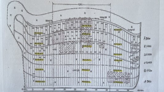
In one of the restoration books is a drawing with the projected view of the shape of the hull plates:
IMG_0310.jpeg
(Source: Restoration book, SZB, page 21)
That will help me when I gonna make the hull plates in the correct shape and position on the frames.
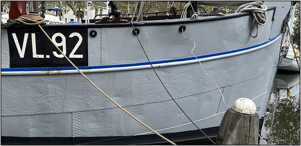
With also this earlier posted picture:
IMG_4191.jpeg
Regards, Peter
 
Last edited:
Back
Top