Tutorial Using the touch probe to setup vise for Proxxon MF70

Jimsky

Administrator
Staff member
Administrator
Forum Moderator
Joined
Nov 3, 2018
Messages
12,278
Points
938

Location
Brooklyn, New York USA
Well, well well... As promised to all of you, who accepted and participated in the vote. Here I am to explain what the heck this tool is for!! I was disappointed with the low count of members who vote. But, I was really happy to know, that none of the voters - doesn't care to find out what is it.

Here is the link to the vote discussion


1659226884293.png

Enough intrigues... and teasers! This tool I called a touch probe. Here, it may be called differently, and most likely won't use the way we used it, but I brought it from my old Country and still use it. Being a quite simple but very important tool. I would like to share the use of it with you.
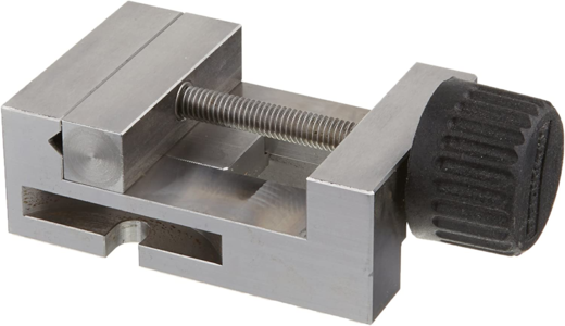
Let's talk about mill setup. BTW, it doesn't have to be a Proxxom mill, it could be any mill with a coordinate (XY) table. Most of the milling operations could be done by using milling clamps, "yea Jim... we all know that. what is the trick?" However, some small parts couldn't be processed in the mill using clamps. Here comes the milling vise to rescue. The milling vise is a special vise. It is usually precisely grounded on all sides where the measurements from the left side are the exact match on the right. Here is the Proxxon milling vise. I measured mine with Mitutoyo caliper, and I was really surprised to find out that my vise is accurate in measurement. :)
1659228654541.png

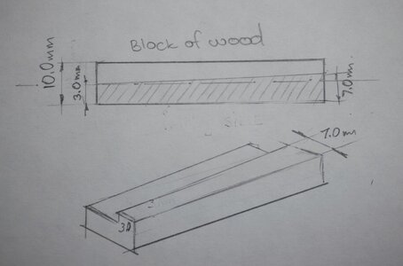
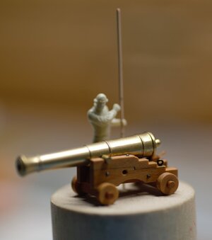
The vise comes with two bolts so you can attach it to the 'X' axis on the milling table. Once attached, you can hold the parts in the vise and...start making some noise. BTW, Proxxon MF70 is somewhat loud... After processing your part, you take the measurements and....Oh...No...Why is the size on one end different than another? Take a look at the sketch below. The block was 10.00mm, I would need a 7.00mm side. 3.00mm I would need to mill, and....what the heck? On one side (start of the mill) it is 7.00mm, but at the end, it is...only 3.00mm. Why is that??? This is a very extreme example, in real life, the differences mostly will be 0.5mm\1.00mm. But, still enough to destroy the part: Say it is the sides for the gun carriage.
600_3095.jpg

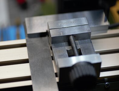
For the machinists the answer is obvious: did you set up your vise? Setup??? What? Why? Yes, my friends, even if you have an Eagle Eye, you must set up your vise against the 'X' axis. In other words, the vise must be 90 degrees to the table. Take a look at the photo below. Do you find the problem there?
600_3098.jpg

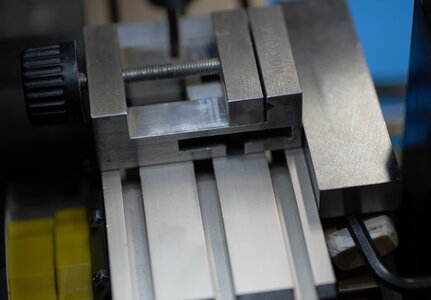
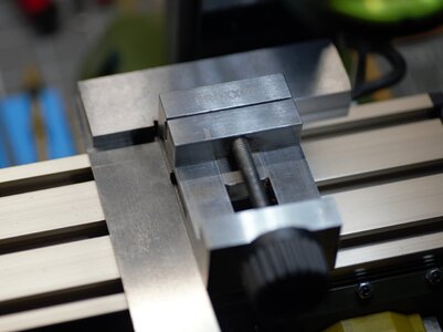
I hope you said "yes, Jim" Why there is a space between the machinist square and vise? And you will be correct. It is the wrong setup. This is why you are getting 7.00mm at the start and 3.00mm at the end. The vise jaws are not parallel to the 'X' axis. I will use the machinists square to correct it. See the photos below.
600_3100.jpg600_3099.jpg

How about now? With this setup, you will have the vise jaws parallel to the table. But wait...I am talking for about 30 minutes, where the heck is your tool?
Well, I would have to explain this first before moving to the actual tool use.
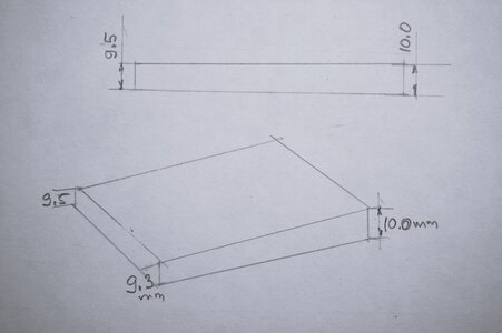
Alright, you set up the vice parallel, you're pretty sure everything will be good now...you have your wood milled again...clean and happy. You took the caliper to measure and...Oh NO...again? Now what? Why the one side is thinner than another? (see the sketch)
600_3096.jpg

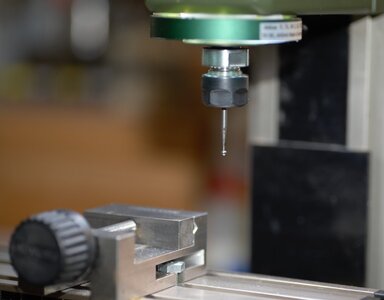
This example is not that extreme in size differences, only 0,3\0.5 mm tenths but... it is enough to destroy your blank for milling the gratings or other parts for your lovely model. Assuming your milling head is not moving while you operate your mill, the problem may come from your XY coordinate table. Yes...but don't panic! Here comes the Touch Probe tool I was messing with you folks about for quite a few days.
600_3074.jpg

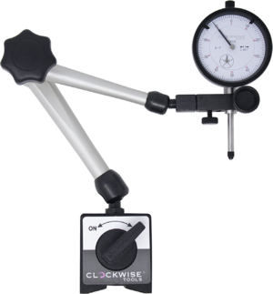
Back in the old days, we don't have good indicators similar to the one below. Still today, the good one can cost half of the Proxxon mills itself. So most of us cannot afford one.
1659235685160.png

So we use the touch probe. It is very simple to use.
1. Attach the probe in the collet, the same way you attach the end mill
2. Move down the mill head 'Z' axis as close as possible until the ball touches the left side of the vise.
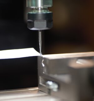
3. Take a piece of printing paper. While adjusting the head (up and down) slide the paper between the ball and the vise until the paper moves somewhat tight.
600_3085.jpg

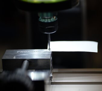
4. Now we have to check another side of the vise. Without touching the milling head ('Z' axis), slide to the next side. But DON'T move the probe on top of your vise. Move out of the vise and then slide to the next side. Once the probe is on top of the next side, slide the paper to check the gap.
600_3079.jpg
If the paper moves much easy, or you can visually see the gap, you will need to put a shim (Russian term). The size of the shim will be determined using your gut feeling. Untighten the screw and put a piece of paper\thin brass plate. Tight the screw again and re-check. Here in the picture below, I have a gap of 0.5mm.
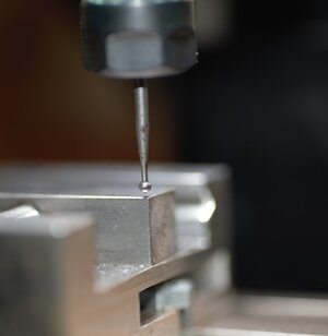
600_3083.jpg

I find a brass shim and put it under that side.

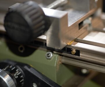
600_3077_1.jpg

Once you set one side, move to another. The goal is that the paper has the same tensions across all 4 sides. It would require some practice, for sure. The first time you might fail, but once you grasp it, the results will be rewarding. Let me know if you have any questions, I'll be more than glad to answer.

Happy modeling!!!

600_3094.jpg 600_3091.jpg
 
Interesting Jim,I am on my second MF70 XY table and second vice as I wore the last ones out.I have not encountered any issues with the vice being out of level in relation to cutter path on either set up.You should not need to do this on any mill of any size.I suspect something else is "off"

Kind Regards

Nigel
 
Great tutorial Jim! BTW Mitutoyo calipers are wonderfully accurate tools.

I did indeed fail to "think outside of the box". As I have a dial indicator I use as an edge finder and determine vice, stock and even initially x, y table to be square with my mill's spindle. I could not get my brain to work abstractly. ROTF What really threw me off was the ball end mounted in a collet directly, not thinking of the low tech way you can do it.

"Necessity is the mother of invention." This is a great demo of how anyone can set up there mill's workspace accurately without high tech tools. Very creative, AND entertaining! See, it does have the "Jimsky" flair to it.

As always, thanks for sharing mate!
 
Well, well well... As promised to all of you, who accepted and participated in the vote. Here I am to explain what the heck this tool is for!! I was disappointed with the low count of members who vote. But, I was really happy to know, that none of the voters - doesn't care to find out what is it.

Here is the link to the vote discussion


View attachment 321091

Enough intrigues... and teasers! This tool I called a touch probe. Here, it may be called differently, and most likely won't use the way we used it, but I brought it from my old Country and still use it. Being a quite simple but very important tool. I would like to share the use of it with you.
Let's talk about mill setup. BTW, it doesn't have to be a Proxxom mill, it could be any mill with a coordinate (XY) table. Most of the milling operations could be done by using milling clamps, "yea Jim... we all know that. what is the trick?" However, some small parts couldn't be processed in the mill using clamps. Here comes the milling vise to rescue. The milling vise is a special vise. It is usually precisely grounded on all sides where the measurements from the left side are the exact match on the right. Here is the Proxxon milling vise. I measured mine with Mitutoyo caliper, and I was really surprised to find out that my vise is accurate in measurement. :)

View attachment 321093

The vise comes with two bolts so you can attach it to the 'X' axis on the milling table. Once attached, you can hold the parts in the vise and...start making some noise. BTW, Proxxon MF70 is somewhat loud... After processing your part, you take the measurements and....Oh...No...Why is the size on one end different than another? Take a look at the sketch below. The block was 10.00mm, I would need a 7.00mm side. 3.00mm I would need to mill, and....what the heck? On one side (start of the mill) it is 7.00mm, but at the end, it is...only 3.00mm. Why is that??? This is a very extreme example, in real life, the differences mostly will be 0.5mm\1.00mm. But, still enough to destroy the part: Say it is the sides for the gun carriage.

View attachment 321096

For the machinists the answer is obvious: did you set up your vise? Setup??? What? Why? Yes, my friends, even if you have an Eagle Eye, you must set up your vise against the 'X' axis. In other words, the vise must be 90 degrees to the table. Take a look at the photo below. Do you find the problem there?

View attachment 321097

I hope you said "yes, Jim" Why there is a space between the machinist square and vise? And you will be correct. It is the wrong setup. This is why you are getting 7.00mm at the start and 3.00mm at the end. The vise jaws are not parallel to the 'X' axis. I will use the machinists square to correct it. See the photos below.

View attachment 321099View attachment 321100

How about now? With this setup, you will have the vise jaws parallel to the table. But wait...I am talking for about 30 minutes, where the heck is your tool?
Well, I would have to explain this first before moving to the actual tool use.
Alright, you set up the vice parallel, you're pretty sure everything will be good now...you have your wood milled again...clean and happy. You took the caliper to measure and...Oh NO...again? Now what? Why the one side is thinner than another? (see the sketch)

View attachment 321109

This example is not that extreme in size differences, only 0,3\0.5 mm tenths but... it is enough to destroy your blank for milling the gratings or other parts for your lovely model. Assuming your milling head is not moving while you operate your mill, the problem may come from your XY coordinate table. Yes...but don't panic! Here comes the Touch Probe tool I was messing with you folks about for quite a few days.

View attachment 321110

Back in the old days, we don't have good indicators similar to the one below. Still today, the good one can cost half of the Proxxon mills itself. So most of us cannot afford one.

View attachment 321111

So we use the touch probe. It is very simple to use.
1. Attach the probe in the collet, the same way you attach the end mill
2. Move down the mill head 'Z' axis as close as possible until the ball touches the left side of the vise.
3. Take a piece of printing paper. While adjusting the head (up and down) slide the paper between the ball and the vise until the paper moves somewhat tight.

View attachment 321112

4. Now we have to check another side of the vise. Without touching the milling head ('Z' axis), slide to the next side. But DON'T move the probe on top of your vise. Move out of the vise and then slide to the next side. Once the probe is on top of the next side, slide the paper to check the gap.

View attachment 321114
If the paper moves much easy, or you can visually see the gap, you will need to put a shim (Russian term). The size of the shim will be determined using your gut feeling. Untighten the screw and put a piece of paper\thin brass plate. Tight the screw again and re-check. Here in the picture below, I have a gap of 0.5mm.

View attachment 321115

I find a brass shim and put it under that side.

View attachment 321116

Una vez que establezca un lado, muévase a otro. El objetivo es que el papel tenga las mismas tensiones en los 4 lados. Requeriría algo de práctica, seguro. La primera vez puede fallar, pero una vez que lo capte, los resultados serán gratificantes. Déjame saber si tienes alguna pregunta, estaré más que feliz de responder.

¡¡¡Feliz modelaje!!!

View attachment 321117 View attachment 321118
Me encanta su explicación si supiera inglés, pero la traducción es tan mala que solo se que habla de fresar una pieza de madera. Lo siento de verdad
 
Interesting Jim,I am on my second MF70 XY table and second vice as I wore the last ones out.I have not encountered any issues with the vice being out of level in relation to cutter path on either set up.You should not need to do this on any mill of any size.I suspect something else is "off"

Kind Regards

Nigel
Hi Nigel. Thanks for the experience and comments. Obviously, something is off, and I know for sure what. It is the coordinate table, specifically the 'X' axis, but it is possible the 'Y' as well. They are not flat. If you take the machinist square, at three different points: both ends and the middle, you might notice the gaps. Perhaps yours might be perfect. I am interesting, however, where did the vise exactly wear?

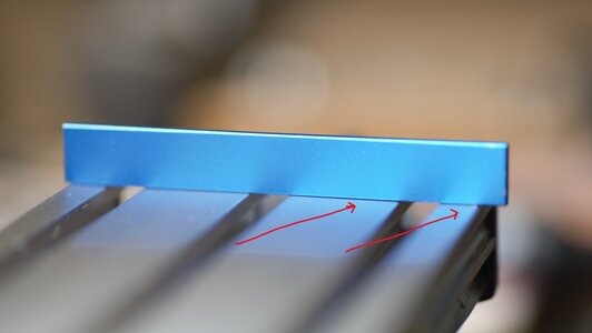
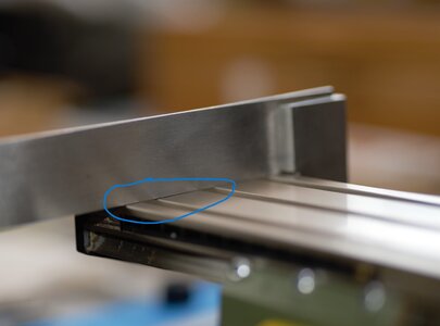
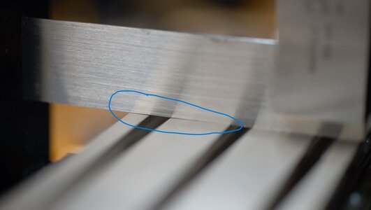
Late Edit: Below is some photos I made to show how the coordinate table is wrong. It is like an airplane propeller

right side
600_3101.jpg

the left side
600_3105.jpg

the middle
600_3106.jpg
 
Me encanta su explicación si supiera inglés, pero la traducción es tan mala que solo se que habla de fresar una pieza de madera. Lo siento de verdad
I am sorry, Juan to know that translation didn't work out well. It is mostly my English and jokes which Google has no clue what do I mean. I hope you can benefit from the images.

Lamento, Juan, saber que la traducción no salió bien. Es sobre todo mi inglés y mis bromas que Google no tiene idea de lo que quiero decir. Espero que puedas beneficiarte de las imágenes.
 
Hi Nigel. Thanks for the experience and comments. Obviously, something is off, and I know for sure what. It is the coordinate table, specifically the 'X' axis, but it is possible the 'Y' as well. They are not flat. If you take the machinist square, at three different points: both ends and the middle, you might notice the gaps. Perhaps yours might be perfect. I am interesting, however, where did the vise exactly wear?

Late Edit: Below is some photos I made to show how the coordinate table is wrong. It is like an airplane propeller

right side
View attachment 321195

the left side
View attachment 321196

the middle
View attachment 321197

Jim the vice wore out on the bushing that holds the moving jaw to the threaded rod meaning you had to prise it open, not helped by corrosion after being stored in a damp garage when I was between workshops.

The XY table wore out on the lead screw nut which is made of nylon and resulted in too much backlash for the readout to be practical.

Looking at your pics that is a bad extrusion.The issues you are experiencing are normally attributed to the column not being 90 to the baseplate or bad machining of the xy table base.

Kind Regards

Nigel
 
Looking at your pics that is a bad extrusion.The issues you are experiencing are normally attributed to the column not being 90 to the baseplate or bad machining of the xy table base.
Thanks, Nigel. The problem is the top of the table. At the moment, I cannot find the youtube video where the guy actually shows how to fix it by reinforcing the aluminum table from the back. I am still trying to find it.

late edit: I found it. Unfortunately, it is the Russian language, but you can watch what he is doing.

 
There are far more experienced tool makers and writers like Tublar Cain, Wingrove (ships and cars)…. And other! I suggest Model engineer set ups and beef up cross table as in screws, vibration etc. But to what degree of accuracy 10,000 inch ? Wobble bar or pointer is far good enough - dial indicator does not cost much. I recommend than the cigarette paper method. Please remember the vertical shaft running vertical (drill bit) + chuck / Collet- dial indicator is a must. Then sim or ground. Rest you can use touch method as by your photos. Collet is far superior to any jaws (lap them / check).
 
Well, well well... As promised to all of you, who accepted and participated in the vote. Here I am to explain what the heck this tool is for!! I was disappointed with the low count of members who vote. But, I was really happy to know, that none of the voters - doesn't care to find out what is it.

Here is the link to the vote discussion


View attachment 321091

Enough intrigues... and teasers! This tool I called a touch probe. Here, it may be called differently, and most likely won't use the way we used it, but I brought it from my old Country and still use it. Being a quite simple but very important tool. I would like to share the use of it with you.
Let's talk about mill setup. BTW, it doesn't have to be a Proxxom mill, it could be any mill with a coordinate (XY) table. Most of the milling operations could be done by using milling clamps, "yea Jim... we all know that. what is the trick?" However, some small parts couldn't be processed in the mill using clamps. Here comes the milling vise to rescue. The milling vise is a special vise. It is usually precisely grounded on all sides where the measurements from the left side are the exact match on the right. Here is the Proxxon milling vise. I measured mine with Mitutoyo caliper, and I was really surprised to find out that my vise is accurate in measurement. :)

View attachment 321093

The vise comes with two bolts so you can attach it to the 'X' axis on the milling table. Once attached, you can hold the parts in the vise and...start making some noise. BTW, Proxxon MF70 is somewhat loud... After processing your part, you take the measurements and....Oh...No...Why is the size on one end different than another? Take a look at the sketch below. The block was 10.00mm, I would need a 7.00mm side. 3.00mm I would need to mill, and....what the heck? On one side (start of the mill) it is 7.00mm, but at the end, it is...only 3.00mm. Why is that??? This is a very extreme example, in real life, the differences mostly will be 0.5mm\1.00mm. But, still enough to destroy the part: Say it is the sides for the gun carriage.

View attachment 321096

For the machinists the answer is obvious: did you set up your vise? Setup??? What? Why? Yes, my friends, even if you have an Eagle Eye, you must set up your vise against the 'X' axis. In other words, the vise must be 90 degrees to the table. Take a look at the photo below. Do you find the problem there?

View attachment 321097

I hope you said "yes, Jim" Why there is a space between the machinist square and vise? And you will be correct. It is the wrong setup. This is why you are getting 7.00mm at the start and 3.00mm at the end. The vise jaws are not parallel to the 'X' axis. I will use the machinists square to correct it. See the photos below.

View attachment 321099View attachment 321100

How about now? With this setup, you will have the vise jaws parallel to the table. But wait...I am talking for about 30 minutes, where the heck is your tool?
Well, I would have to explain this first before moving to the actual tool use.
Alright, you set up the vice parallel, you're pretty sure everything will be good now...you have your wood milled again...clean and happy. You took the caliper to measure and...Oh NO...again? Now what? Why the one side is thinner than another? (see the sketch)

View attachment 321109

This example is not that extreme in size differences, only 0,3\0.5 mm tenths but... it is enough to destroy your blank for milling the gratings or other parts for your lovely model. Assuming your milling head is not moving while you operate your mill, the problem may come from your XY coordinate table. Yes...but don't panic! Here comes the Touch Probe tool I was messing with you folks about for quite a few days.


Back in the old days, we don't have good indicators similar to the one below. Still today, the good one can cost half of the Proxxon mills itself. So most of us cannot afford one.


So we use the touch probe. It is very simple to use.
1. Attach the probe in the collet, the same way you attach the end mill
2. Move down the mill head 'Z' axis as close as possible until the ball touches the left side of the vise.
3. Take a piece of printing paper. While adjusting the head (up and down) slide the paper between the ball and the vise until the paper moves somewhat tight.


4. Now we have to check another side of the vise. Without touching the milling head ('Z' axis), slide to the next side. But DON'T move the probe on top of your vise. Move out of the vise and then slide to the next side. Once the probe is on top of the next side, slide the paper to check the gap.


If the paper moves much easy, or you can visually see the gap, you will need to put a shim (Russian term). The size of the shim will be determined using your gut feeling. Untighten the screw and put a piece of paper\thin brass plate. Tight the screw again and re-check. Here in the picture below, I have a gap of 0.5mm.


I find a brass shim and put it under that side.


Once you set one side, move to another. The goal is that the paper has the same tensions across all 4 sides. It would require some practice, for sure. The first time you might fail, but once you grasp it, the results will be rewarding. Let me know if you have any questions, I'll be more than glad to answer.

Happy modeling!!!
So the idea is to check all 4 corners of the vice, correct?
 
Thanks, Nigel. The problem is the top of the table. At the moment, I cannot find the youtube video where the guy actually shows how to fix it by reinforcing the aluminum table from the back. I am still trying to find it.

late edit: I found it. Unfortunately, it is the Russian language, but you can watch what he is doing.


Interesting video Jim and some serious distortion on the extrusion.I did think that if I came across the issue I could clamp the whole table into my big mill and face it off flat. Only thing against that is I bet the extrusion is hard anodised and I will loose that wear resistant surface.

Kind Regards

Nigel
I would completely agree with your task, even taking into account the sickness after the face-it-off. But... in the end, you will have an absolute parallel table against your big mill and not the Proxxon's. Ideally, it would be awesome to shave the table in the Proxxon itself. :cool:
I do understand that Proxxon is more a toy than an actual tool. When it comes to precision, we should only expect a certain degree of it. Even considered it is a toy, it becomes my desktop toy tool. This is why we have a series of blogs called Can you get the most out of your Proxxon MF70? Articles collected and shared the ideas of various jigs and upgrades for this small mill. The biggest upgrade I made on my Proxxon, no... not converted to CNC, I changed the spindle to accept the ER11 collect system. Now, it accepted the endmills up tofrom 1.00mm to 7,0mm. Thanks, @Tobias who bought and shipped it from Germany. Even thought the biggest endmill I use (thus far) it 5.00mm but it gives a broad range of endmills to use compare to originals collet system comes factory shipped.
 
Jim,
Should we not follow the same procedure after positioning a piece in the vise? The vise could be perfectly aligned but the piece to be milled may not have been clamped accurately.
 
Jim,
Should we not follow the same procedure after positioning a piece in the vise? The vise could be perfectly aligned but the piece to be milled may not have been clamped accurately.
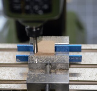
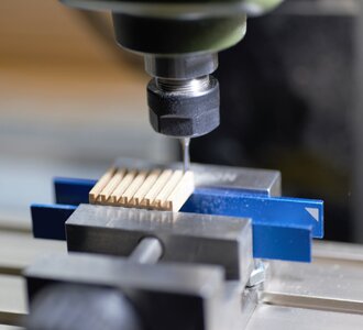
Actually, this is a great question, Algol. Honestly, I was waiting for someone should ask. When you need to mill the material in the vise, you would need to find or let's say make it as the absolute 0 (zero) or base. Such a surface is usually perfectly flat and square. Milling the base is just a matter of tightening the part in the vise, parallel (eyesight) to the jaws, and passing the endmill until the surface is flat. I am sure you would say, "Jim, I get it" However, in many cases, parts do not naturally sit above the top of the vise jaws where surface milling operations require them to be. Parallels are used to raise the work above the vise jaws for surface machining and drilling operations. Parallels are coming in matching sets. Check this video, you will have a good understanding. I use aluminum sanding sticks 5.0mm and 10.00mm acquired on AliExpress. Here I am using those sanding sticks as Parallels to make a 'base' on the block of Pearwood.

600_2927.jpg 600_2929.jpg

Here is the video

 
Back
Top