Soleil Royal by Heller - an Extensive Modification and Partial Scratch-Build by Hubac’s Historian

Marc,
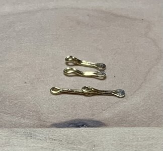
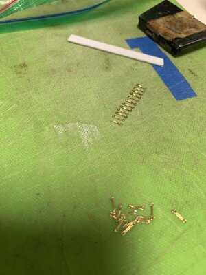
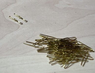
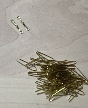
I assume these pieces are hard soldered, right? Did you try it with less paste? With this much it looks like soft soldering and the surplus paste has to be removed anyhow. Sorry, did not want to be critical (you have been doing a great job), just my 2 cents...
János
Hello Janos,

I'm sorry for the late reply. I don't even receive updates on my own build, let alone anyone else's. I continue to be pre-occupied with life.

Yes, I have been using the solder paste, which I find much easier to deal with than regular solder. You are right that there was significant cleanup on my deadeye strops. I have taken to applying minute solder amounts with the tip of a #11 blade, so as to better control the application. This has been working well for me on the preventer plate links.

No real progress to show, though.
 
That may very well be the case, Chris, but from a practical standpoint, it would seem to be counter-productive as the iron would quickly degrade in a marine environment, and the entry of the iron into the ship timbers would not be adequately sealed without a paint topcoat.
Some of the early smelting methods produced iron of quite high purity which is actually remarkably corrosion resistant. When using similar fastenings on medieval wooden bridges in the UK the holes were doped with tallow and the iron fastenings driven in hot. The molten wax sealed the end grain of the wood fibres and also prevented corrosion of the hidden part of the metal fixings. Some of these fastenings - and the wood they were driven - into were retrieved intact from the Thames in London a few years ago, after 800 years buried in the salty mud of a tidal estuary. There is a saying 'old iron never rusts' which may be appropriate.
 
That is interesting insight, Alan, and I don’t doubt it. It is known, however, that the French thoroughly painted the so-called deadworks of their ships; this would be everything above the waterline.

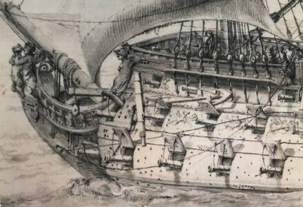
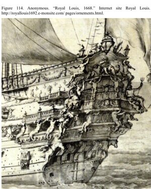
The portrait of the Monarque that Chris is writing about is unusually detailed, although not so unusual for Puget. Some, particularly those who support the notion that these Vienna portraits represent the Royal Louis, suggest that the relatively bright appearance of the hull may indicate the white paint that the RL was originally cloaked in. Perhaps the Monarque, constructed at the Toulon arsenal at the same time as the RL, was also painted all white. A detailed written description of the outward appearance only exists for the RL, though, in the form if the Hyatt monograph.

IMG_1582.png
IMG_3822.jpeg
IMG_0173.jpeg

My theory about the appearance of the drawings above is that the apparent brightness of the ship merely indicates the underlying color of the drawing surface, or medium.

This is consistent with other Puget drawings:

IMG_2461.jpeg
 
My theory about the appearance of the drawings above is that the apparent brightness of the ship merely indicates the underlying color of the drawing surface, or medium.
I think you are probably right about that, the only reason to doubt it is that while lead and boiled linseed oil were easy to make early paints, and provided some limited protection against shipworm. But in the absence of any surviving fragments of the true cross, we cannot really be sure.;)
 
I can’t escape the fact that I continue to fail at this chain-making exercise. As the old maxim goes, though, every failure is one step closer to success.

I’ve now thrown away two whole batches of chain preventer plates. While I was quite right to follow Andre Kudin’s example, for the process of their manufacture, I eventually discovered that that process is not entirely transferable from 1:48 to 1:96 scale.

After forming his basic links, Andre solders them closed at one end, and then places the closed link back onto the two pins so that he can crimp an eye on each end with his round pliers.

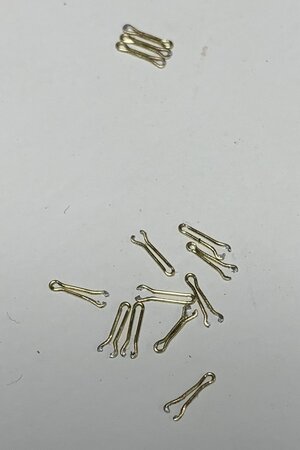
Well, the 28 gauge brass wire I’m using does not provide enough surface area for a strong enough bond to survive the crimping. My success to failure ratio was pretty poor:

IMG_6177.jpeg

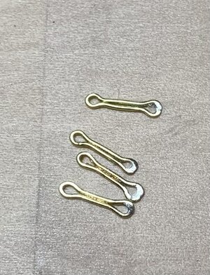
So, my lesson from that exercise was that I needed to do the crimping before soldering one end closed:

IMG_6200.jpeg

These soldered loops will be the lowest end of the chains, bolted into the wales. That way, I could induce a series of bends into the upper half of each preventer plate, so that they could overlay the next small link:

IMG_6201.jpeg

Above I’m just using another preventer plate to check that the bends I’m making are sufficient.

So, I spent a good chunk of time cleaning up the solder and inducing bends into the remainder of the preventer plates. The solder joint will be re-enforced with the CA glue that fixes the pin-bolt in place:

IMG_6212.jpeg

With that out of the way, I could make a new, slightly closer-spaced pin jig for the next small link, which is only crimped on one end, where it seats beneath the preventer plate.

Now that I have a process that I know will work, and now that I’ve had all of this practice, these next links should go fairly quickly:

IMG_6214.jpeg
IMG_6215.jpeg

I have a lot of these to make, solder and bend - about 70 to ensure I can use the best. This has all been a colossal PITA, but it was really important to me that all of this look very clean and uniformly shaped. In the process, I have acquired some very valuable metal skills that will only enhance this and future projects.

That said, I am going to experiment with using black nylon thread of an appropriate diameter to connect the deadeye strop loops to the small links. This would essentially be a variation on the way that the stock kit represents these links, but I will do individual chain loops that draw tight with some form of slip-knot that I can pull up and hide behind the deadeye strop.

Andre had a great method for producing these variances, but it is all just that much more tedious in the smaller scale.

The advantages of doing this are several. So long as there is not a jarring difference in appearance between the black thread and the blackened metal, it will save me tremendous amounts of time. It also simplifies the difficulty of accurately measuring and keeping track of a series of increasingly longer links as the shroud angle increases from fore to aft. Lastly, it greatly simplifies the placement of the deadeyes because I can add the retaining strip, in advance, and it also makes it much easier to locate and properly secure the bottom two links. Hopefully, that will work out.

Well, I keep saying that I’m going to get back in the swing of the project, and then I get sucked into coaching another basketball team - now my son’s Spring rec team. Meanwhile, the Rangers and Knicks are just too compelling to ignore this post-season. At least for now, I can see the end of the tunnel for these chains, which is tremendously motivating, and then I can return to the more immediately gratifying work of outfitting and arming the main deck.

Thank you all for taking the time to look back in on This Old Build. More to come!
 
I can’t escape the fact that I continue to fail at this chain-making exercise. As the old maxim goes, though, every failure is one step closer to success.

I’ve now thrown away two whole batches of chain preventer plates. While I was quite right to follow Andre Kudin’s example, for the process of their manufacture, I eventually discovered that that process is not entirely transferable from 1:48 to 1:96 scale.

After forming his basic links, Andre solders them closed at one end, and then places the closed link back onto the two pins so that he can crimp an eye on each end with his round pliers.

Well, the 28 gauge brass wire I’m using does not provide enough surface area for a strong enough bond to survive the crimping. My success to failure ratio was pretty poor:

View attachment 443656

So, my lesson from that exercise was that I needed to do the crimping before soldering one end closed:

View attachment 443657

These soldered loops will be the lowest end of the chains, bolted into the wales. That way, I could induce a series of bends into the upper half of each preventer plate, so that they could overlay the next small link:

View attachment 443655

Above I’m just using another preventer plate to check that the bends I’m making are sufficient.

So, I spent a good chunk of time cleaning up the solder and inducing bends into the remainder of the preventer plates. The solder joint will be re-enforced with the CA glue that fixes the pin-bolt in place:

View attachment 443654

With that out of the way, I could make a new, slightly closer-spaced pin jig for the next small link, which is only crimped on one end, where it seats beneath the preventer plate.

Now that I have a process that I know will work, and now that I’ve had all of this practice, these next links should go fairly quickly:

View attachment 443653
View attachment 443652

I have a lot of these to make, solder and bend - about 70 to ensure I can use the best. This has all been a colossal PITA, but it was really important to me that all of this look very clean and uniformly shaped. In the process, I have acquired some very valuable metal skills that will only enhance this and future projects.

That said, I am going to experiment with using black nylon thread of an appropriate diameter to connect the deadeye strop loops to the small links. This would essentially be a variation on the way that the stock kit represents these links, but I will do individual chain loops that draw tight with some form of slip-knot that I can pull up and hide behind the deadeye strop.

Andre had a great method for producing these variances, but it is all just that much more tedious in the smaller scale.

The advantages of doing this are several. So long as there is not a jarring difference in appearance between the black thread and the blackened metal, it will save me tremendous amounts of time. It also simplifies the difficulty of accurately measuring and keeping track of a series of increasingly longer links as the shroud angle increases from fore to aft. Lastly, it greatly simplifies the placement of the deadeyes because I can add the retaining strip, in advance, and it also makes it much easier to locate and properly secure the bottom two links. Hopefully, that will work out.

Well, I keep saying that I’m going to get back in the swing of the project, and then I get sucked into coaching another basketball team - now my son’s Spring rec team. Meanwhile, the Rangers and Knicks are just too compelling to ignore this post-season. At least for now, I can see the end of the tunnel for these chains, which is tremendously motivating, and then I can return to the more immediately gratifying work of outfitting and arming the main deck.

Thank you all for taking the time to look back in on This Old Build. More to come!
WHO SAID you have to put the seam at the top of one of the loops? Getting the loop at that location to be circular is VERY difficult, and filing away excess metal to open the hole in the loop to accept the pin and removing any blobs there is quite tedious. The eye joint is at the location of greatest stress while you bend the link to it's final shape, and the joint will often break.

Form the loops by wrapping the wire around a drill bit at each end (make a jig) and locate the seam in the centerpoint of one of the straight sections. When filled with solder, the entire link can be made to look like a flat plate between the loops, and not two rods of metal. The solder joins the straight wire sections and the ends of the wire at the seam. Soldering at the loop only adheres the ends of the wire at the loop, and often fills the hole, which is annoying to drill the solder out of. Getting the ends of the straight sections to line up at the seam is straightforward using two sets of small, smooth jawed needle nosed pliers (jewelers pliers).

Work and squeeze the wire using the pliers at the straight section to get the wire to lay perpendicular, with full contact along its length and no gaps. The loops will both have the same size and shape, and it is easier to remove excess solder at the straight section of the piece. Try making a couple this way and see if it's easier. Brass wire and solder are cheap. After soldering, then you can bend the entire piece to create the slope from one eye to the next, so it overlaps the other chainplate piece properly and also lays flat in the hull to accept the pin.
 
Last edited:
Honestly, Kurt, nobody told me I had to do it this way. My experience, though, has shown me that this is an effective method to get the clean appearance that I am after.

What you are proposing is absolutely, technically correct. This was actually what I did on my first attempt of these preventer plate links. There were a couple of problems though. Firstly, I miscalculated the scale and made the links far too long. Second, I could have been more liberal in my application of the tube solder, on the back side of each link. Had I done so, I may not have had as many join failures.

My chief complaint with doing it this way was that I found it quite difficult, at the time, to neatly snip the wire ends, mid-link, for a neat join; I was either too long, which resulted in a bulged middle, or too short, which resulted in an excess of solder. As it usually goes with this sort of thing, I have now become quite adept at gauging where to snip, and I could probably do this much more efficiently now.

In fact, at our club meeting this past week, my friend suggested that he cuts these ends on a long bias, so that they overlap like a scarf join. Again, the larger the scale you are working in, the easier it is to gauge the cuts.

You have to remember that the scale is small. These links are about the smallest things that I can still manipulate with my fingers. I watch a lot of people make chains, in small scales, using the technically correct method and their results are often highly variable.

That was the appeal of Andre's method. When you are bending individual short lengths of wire around your pin formers, you are going to get much more taught bends than you will if you wrap a long length of wire around a former of the desired width. Again, I had been down this road and found it difficult to straighten the long parts of the link, after separating the links.

Lastly, I have not found it to be much work to clean up the solder around the eye. A few swipes on each broad surface, with an emory board will level the solder there, and then I just use an appropriate micro drill bit in a pin vise as a file to open the eye again. Just a few strokes and it's done.

I'm not concerned about the strength of this eye-join because it has held up to my hand manipulation, for one, and it will be re-enforced with CA, when I bolt these parts to the wales. Some builders at this scale eschew solder, altogether, and close their links with CA alone.

At the end of the day, this is a process that is working for me and producing a result that I am very happy with. Eventually, when I build in a larger scale (probably precipitating a divorce from my currently loving wife), I might switch to what is more technically correct.

In this scale, though, I think that clean and uniform work is more important than rigorous accuracy.
 
Back
Top