This will be a very short build log for the pilot boat Achilles of 1815. The model continues my series of sloops and schooners many of which I have described in more extensive logs, and I really have nothing new to say about my modeling methods.
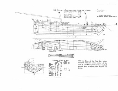
In looking for a new project, I came across the plans for the Achilles shown below in Chapelle'sbook “The Search for Speed Under Sail”.
This vessel has special significance for me because it was my very first model of some 45 years ago. I was so thrilled at turning a box of parts into a recognizable ship that I fell in love with the hobby. Achilles was built from the Mantua kit back in the time when lasers, let alone laser cutting and CAD, were not yet even in the physicist's dreams. All of the parts were printed on wooden sheets and had to be cut out. Modeler's were made of tough stuff in those days. Mantua is still making this kit, and as can be sen in the photo
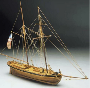
They have modified the deck plan and rigging as compared to the Chapelle plan. It's hard to say what else might have been changed.
Construction was by the plank on bulkhead method in 1/70 scale which gave a 12” hull length. The hull is now complete and masting and rigging are just getting underway. Building was straightforward except for the transom area which had me scratching my head for quite awhile. As can be seen in the plans, the transom consists of two sections at different angles to the deck. The lower section begins right at deck level. My usual procedure is to attach the transom first and then butt the ends of the bulwark planking against it. But in this case there is nothing to attach the transom to. An alternate would be to do the planking first but it would have been tricky to get the compound angles correct
My solution was to add two knees, not in the plans, for transom support as shown in the below photo of the stern area.
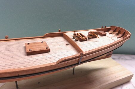
The lower section of the transom was attached to these knees and then the bulwark planking was added to the level of the top edge. The upper section of the transom was then glued to both the knees and the lower section, and planking completed.
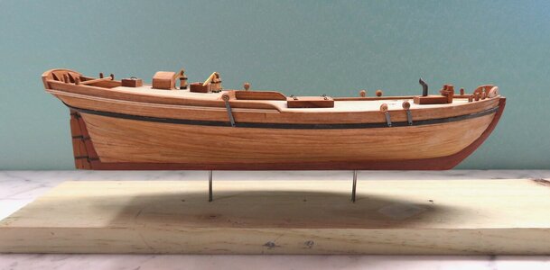
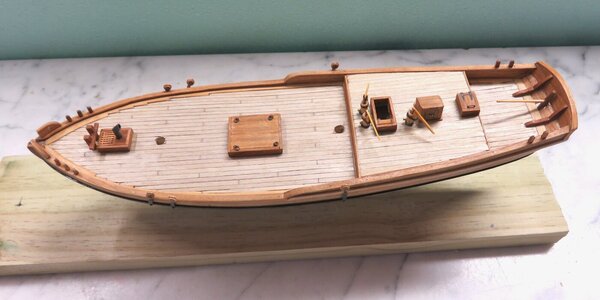
Photos of the completed hull are shown below. As with my other small models, the rudder hinges are blackened paper to be in scale and the rudder is attached to the hull by pins placed in the leading edge and glued into mating holes in the stem. An unusual (to me) feature of the deck is an extra pump on the port side. Achilles must have been leaky.
In looking for a new project, I came across the plans for the Achilles shown below in Chapelle'sbook “The Search for Speed Under Sail”.

This vessel has special significance for me because it was my very first model of some 45 years ago. I was so thrilled at turning a box of parts into a recognizable ship that I fell in love with the hobby. Achilles was built from the Mantua kit back in the time when lasers, let alone laser cutting and CAD, were not yet even in the physicist's dreams. All of the parts were printed on wooden sheets and had to be cut out. Modeler's were made of tough stuff in those days. Mantua is still making this kit, and as can be sen in the photo

They have modified the deck plan and rigging as compared to the Chapelle plan. It's hard to say what else might have been changed.
Construction was by the plank on bulkhead method in 1/70 scale which gave a 12” hull length. The hull is now complete and masting and rigging are just getting underway. Building was straightforward except for the transom area which had me scratching my head for quite awhile. As can be seen in the plans, the transom consists of two sections at different angles to the deck. The lower section begins right at deck level. My usual procedure is to attach the transom first and then butt the ends of the bulwark planking against it. But in this case there is nothing to attach the transom to. An alternate would be to do the planking first but it would have been tricky to get the compound angles correct
My solution was to add two knees, not in the plans, for transom support as shown in the below photo of the stern area.

The lower section of the transom was attached to these knees and then the bulwark planking was added to the level of the top edge. The upper section of the transom was then glued to both the knees and the lower section, and planking completed.
Photos of the completed hull are shown below. As with my other small models, the rudder hinges are blackened paper to be in scale and the rudder is attached to the hull by pins placed in the leading edge and glued into mating holes in the stem. An unusual (to me) feature of the deck is an extra pump on the port side. Achilles must have been leaky.


