HMS Blandford

Joined
Aug 11, 2023
Messages
89
Points
88

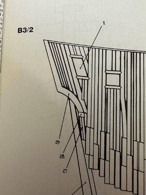
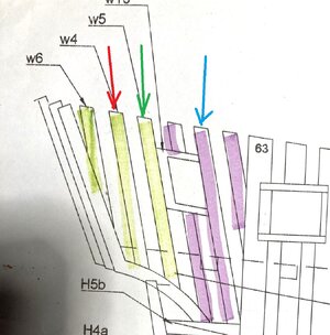
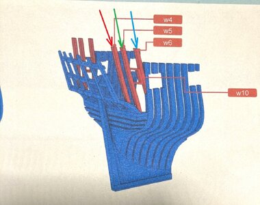
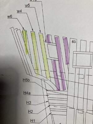
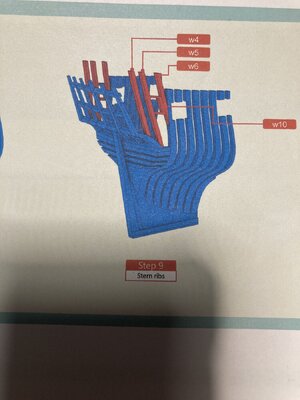
Not sure if I'm posting this in the right spot so please advise if not. I'm confused about the framing for the Blandford at the stern. When I look at the plans for hull construction pieces W4, W5, and W6 are aft of frame 63. But in the "Modeling instructions" it seems to show that W6 is actually attached to 63. If the hull construction sheet is accurate what pieces go where I've highlighted in purple? Are there other pieces that I'm missing? Also what is C1 and C2 for? Is it only for shaping the 3 W7 pieces?

Any and all comments, suggestions, instructions are welcome.

Thank you!
IMG_1293.jpegIMG_1295.jpegIMG_1296.jpeg
 
Hi Craig,

I'm not sure if it helps, or confuses the issue, but here is a pic of part of the frames plan in the "Antomy of the Ship" on the Blandford.
Blandford plans pic.jpg
 
Not sure if I'm posting this in the right spot so please advise if not. I'm confused about the framing for the Blandford at the stern. When I look at the plans for hull construction pieces W4, W5, and W6 are aft of frame 63. But in the "Modeling instructions" it seems to show that W6 is actually attached to 63. If the hull construction sheet is accurate what pieces go where I've highlighted in purple? Are there other pieces that I'm missing? Also what is C1 and C2 for? Is it only for shaping the 3 W7 pieces?

Any and all comments, suggestions, instructions are welcome.

Thank you!
View attachment 424426View attachment 424427View attachment 424428
Hi Craig, If it helps I’ve posted a complete detailed build log of Blandford, I too found that part confusing so I’ve shown it clearly in one of the posts, it works out quite well and isn’t difficult. Ken
 
I can try based what I can see

bland 1.jpeg
bland2.jpeg

To identify these three timbers

Sorry the shown wooden pieces shown in your third photo I can not recognize what it is
 
Hi Craig, Sorry fot the confusion, please follow the way shown on the instructions, there were errors on the drawings and we have fixed on the latest version. C1 and C2 are molds, that are used to shape (bent) the upper transoms. You can check page 20 of the instruction for specific usage. Hope this helps.
 
Hi Craig, If it helps I’ve posted a complete detailed build log of Blandford, I too found that part confusing so I’ve shown it clearly in one of the posts, it works out quite well and isn’t difficult. Ken
Thanks Ken for your reply. I‘ll look for the log. Note that Modelship Dockyard acknowledged the plans were flawed. And Corsair I have the Blandford Anatomy of the Ship but it didn’t help me. Thank you.
 
Back
Top