Hancock

Dave Stevens (Lumberyard)

Sponsor: dlumberyard
Staff member
Sponsor
Joined
Dec 1, 2016
Messages
5,131
Points
728

just sitting here thinking now what should i do?

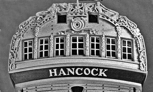
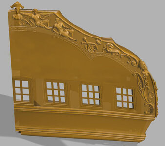
Well i am thinking i will start 2 projects at once i just finished this CAD stern drawing for the Hancock an American frigate and it is ready to move on to 3D modeling
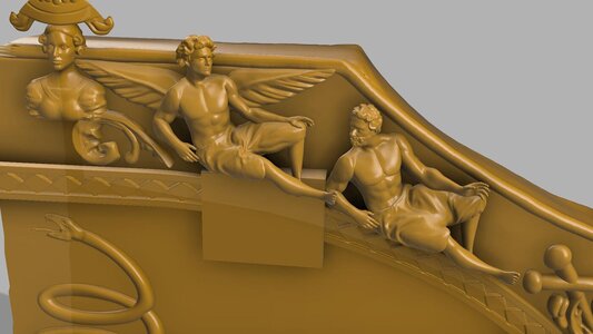
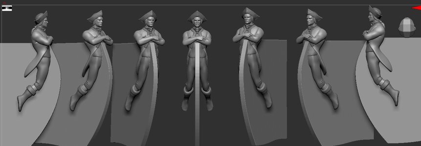
i also have a stern of the Alfred at the laser cutter so it is ready to start building, all the stern decorations have been 3D modeled and ready for printing.

i do like working on more than one project at a time because some days i feel like drawing and other days i feel like building. i still have the quarter gallery to draw then all the framing for laser cuttung, so lots of drawing time.

maybe if there is an interest i might do a limited edition of the 2 projects.

and then again the wife says "you been sitting at that computer for 3 days, don't you think you should find something else to do besides sitting?"
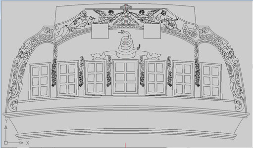

hancock stern2.jpg
 
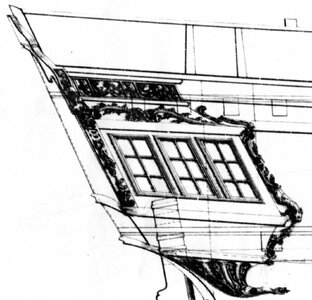
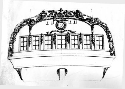
i was going through Harold Hahns library and found a copy of the original Admiralty drawing of the Hancock

img337.jpg

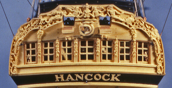
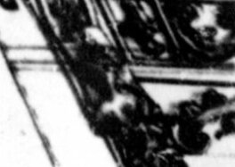
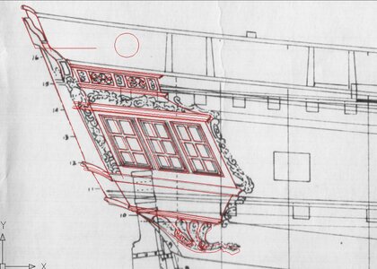
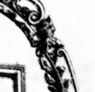
the problem when i redrew the stern the figures at the side taking a closer look who are these figures?

the Hancock was american built in 1776 so what figures would have been carved on the stern?

img337c.jpgimg337cl.jpg

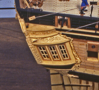
my first guess was a Roman soldier but now i think that is wrong because the view of the gallery i think i see it might be female figure.

do you think it is just a random bust of some ones wife, a mermaid, a roman goddess

img609.jpg
hk02c.jpghk03c.jpg

buy the way wrong snake i got to change that

img338.jpg

img338c.jpg
 
here is an interesting development plans drawn by hand vs plans drawn by CAD computer aided drafting

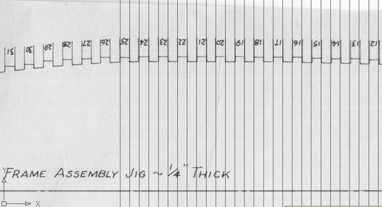
we are looking at the framing jig which Hahn drew with 1/8 frames and 1/8 space starting at frame 25 it is right on now look close at 14 and 13 they re so slightly off

jig1.JPG

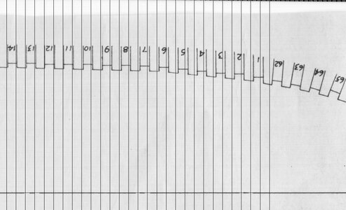
the smallest error begins to compound itself, look what happens when you reach frame 1 it is almost a full frame off the mark

jig2.JPG

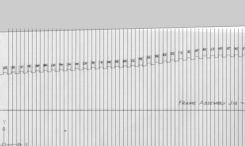
lets go to the stern from frame 25 and frame 52 is almost a full frame to long there is another 9 frames before you hit the stern so the stern if you line up frame 1 will be 1/4+ to long

i think 1/8 inch = foot is to small a scale to work in so i will take the drawings and blow them up to 3/16 scale and that 1/4 inch will now be 3/8 to long.

the wy to fit it is to continue the entire drawing in CAD and collrect the errors so everything will fit

the creeping thousandth caught ya!

jig3.JPG
 
the trick in drawing in 2D you have to think in 3D and lay out the drawing in top, side and front views

in Hahn's original drawings the top view does show the side of the hull but not the gallery

top view.JPG

the information is actually in the drawing you just have to project it so the 3D modeling can be done


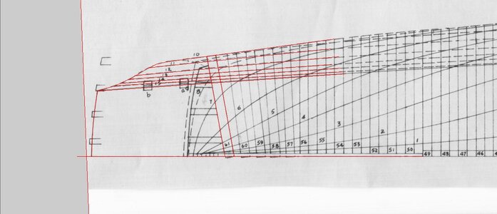
how to do that? notice the numbers at the stern those are the same as the red lines in the top view but from a side view

gallery1.JPG
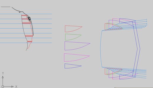
t ook those lines turned them blue and layed them on a stern view

gallery3.JPG

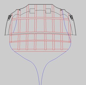
here is the stern view the blue curved line is the hull the black shape of the stern is over layed on the stern frames. The distance from the blue hull line to the black stern gives me the vertical lines of the gallery the horizontal lines come from the side view drawing of the gallery. Now i can project the shape of the gallery.

gallery4.JPG

piece by piece the parts are projected in the top, side, back and front views and from this information a 3D model begins to take shape.

Harold Hahn plans do give you the informtion needed to build a model as long as you have drarting skills to create all the patterns needed.
 
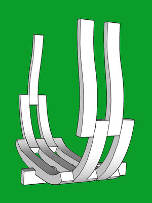
first thing was to establish the framing of the hull notice the red line above the caprail, i extended the frames to this line which is 1/4 inch above the final top of the frames. i did this as a buffer zone so when the frames are set in you can be sure the frames will not fall short of the caprail.

framing.JPG

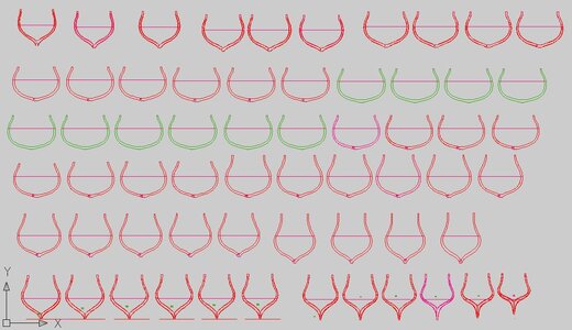
then to draw out all the frames the line running through all the frames is the location of the jig


frames.JPG

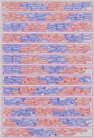
once all the frames are drawn out i broke them down into their parts and layed thre parts out on sheet for laser cutting

full frames.JPG

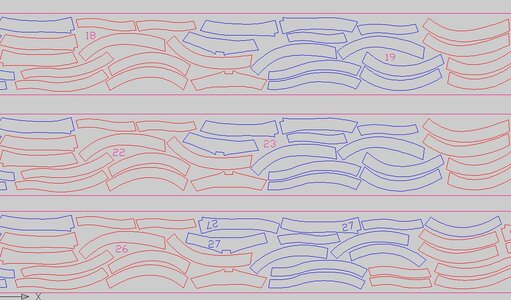
taking a closer look you can see how the frame parts are nested together, the red and blue color seperates each frame. if the drawing was all one color it would be almost impossible to know what parts goes to what frame.

full frames2.JPG

the next step is the draw the framing jig
 
Last edited:
the Hahcock started out with the idea to be a reproduction of Harold Hahn's model using his plans. As the drawing progressed it became clear that would not work out. first the addition of the extra extensions above the frames to fit in a jig added a lot of material and laser cutting. So the extension of the frames were scrapped and the jig moved down along the hull.
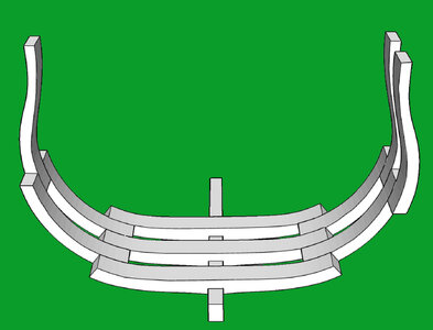
The next issue was the size and spacing of the frames, Hahn used the admiralty style of room and space where the space is equal to the frame size. The style is correct but the building method is not. In admiralty framing the futtocks set between the floors Here is an example

frameshape1C.jpgframeshape1D.jpg

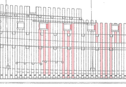
the room and spacing did not line up with the gun ports and Hahn ended up cutting into frames and adding filler. Besides that, hulls for war ships were not built using the room and spacing. The framing was much heavier with only inches between frames.

hancock hahn framing.jpg

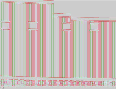
in this version of the Hahcock the framing is much heavier and the space between frames much smaller bring the framing closer to how the Hancock was built. also by changing the size and spacing of the frames the gun posts now line up with the sides of the frames

new framing.JPG
 
The Hahcock build is being designed for a how to build a framed model of an Americam built frigate. There is a kit of the Confederacy but it is a plank on bulkhead showing a section of framing at the mid ship which is an English style of framing which was never used in Americam build frigates. So as far as i know this is a first of its kind. If all goes as planned there will be cast stern carvings and figurehead, laser cut framing, jig, deck beams and keel structure. The idea is to guide a builder step by step piece by piece to build a first class model. You really can not go wrong because every part is replaceable .I am also keeping in mind the cost for a semi-kit trying to make the build project affordable.
 
because this project is being designed as a future kit and SoS on line build i have to conside the final cost of a semi-kit. I suspect if the final cost is $1,600.00 many builders are going to back off because it is a bit to expensive. but as i draw and design parts i can see the cost of laser cutting getting higher and higher then the cost of 3D modeling, making molds and casting resin , cost of wood, Mill work for planking etc.

take a look at Harold Hahn's model of the Hancock

for this to be a first class high end plank on frame model what would you as builders consider just to expensive and at the other end what you consider a deal to good to pass up? Lets put a range on price from $600.00 to $2,000.00

there would be no rigging just a hull model a rigging set would be available as an add on.

what would be included are laser cut framing you have to build up the frames. fittings like the capstan, guns and carrages. hull planking from the wales to the caprail, decking, figurehead and stern carvings.

a designer and fabricator can go hog wild and design with a disregard to the final cost. As a CAD draftsman i work for $70.00 an hour so it is what it is, take it or leave it. OR i can think to myself with a couple 100 hours there is no way i would make $70.00 an hour, so 90% is a labor of love and bringing something to the community of model ship building.
 
one more thing is the model is in 3/16 scale with a 30 inch hull Hahn did his model in 1/8 scale which is a 20 inch hull but at that scale the parts are really small. I thought if a 1/4 scale but that is a 40 inch hull which is quite big for home display.
 
Given the rising cost of both high quality POB and POF models, I would expect a cost of around $1,000 or more to be reasonable. I built the Oneida from Lumberyard years ago and a similar kit for Hancock would be great.
 
i have not finished all the cad work and laser cutting files for the framing but i hope to keep this cost way down.
the biggest cost was the 3D sculpture work and 3D printing but i took the leap into 3D printing which cost much less when done in house.

i can never hope to be paid for the time i put into this but that does not matter because i would do it anyhow as a hobby.

i would like to do a limited run of plank on frame kits of the Hancock for around $600.00 which today is not to bad considering a Mc Donalds big Mac is going on up to $18.00 due to the rise in minimum wage to $20.00 an hour.
 
from tests i have done using a .04 nozzle i am thinking maybe for better detail i should use a .02 and make the slicing much finer. I do have 3 settings normal, fine and high quality. time to experiment
 
Back
Top