French heavy frigate of 1686 - designing a ship in the Dutch(?) manner by graphic means

Joined
Apr 26, 2023
Messages
383
Points
323

Location
European Union
.​

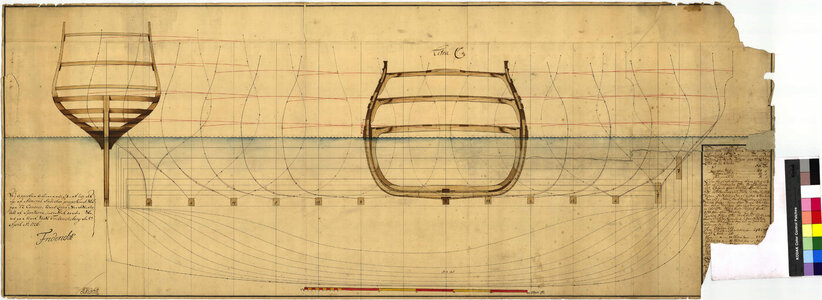
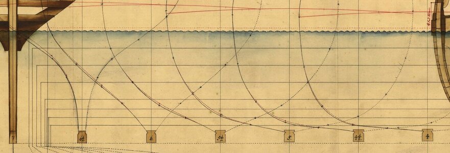
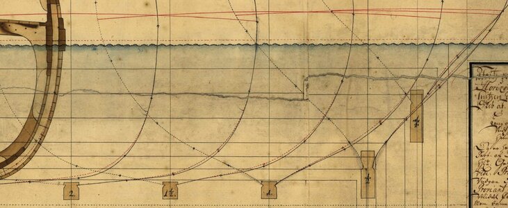
This plan of a heavy frigate, drawn up by the French shipwright P. Chaillé in 1686, is a real gem. First of all, until now it was virtually unknown what conceptual methods were used on the Atlantic coast of France (Ponant) until the very last years of the 17th century, that is, until the widespread and already complete adoption of methods based on the harmonious division of design diagonals.

Secondly (somewhat retrospectively at this point), it perfectly shows how the methods known to be practised in the southern region of the Netherlands during this period, as described by van Yk, were already applied in an entirely graphic manner by the professional shipwright of the time. Or perhaps it would be better to say that it is not at all a strictly Dutch method, but in fact a common good, applied and developed throughout the entire north of the continent (i.e. on the coasts of Germany, Netherlands, France and Scandinavia), with varying degrees of intensity in the different areas at different times.

It can also be said that this plan allows for a better understanding of the conceptual design tools with which it would be possible today to graphically reconstruct the shapes of ships built in the ways described particularly in the two monumental 17th century Dutch works on shipbuilding and implied by the French royal ordinances of this period.

This plan has already been covered in some detail in the monograph La frégate. Marine de France 1650–1850 by Jean Boudriot, albeit without a detailed explanation of the conceptual method actually employed by its 17th century creator, which can only be recognised through a rather painstaking graphic analysis of the plan.
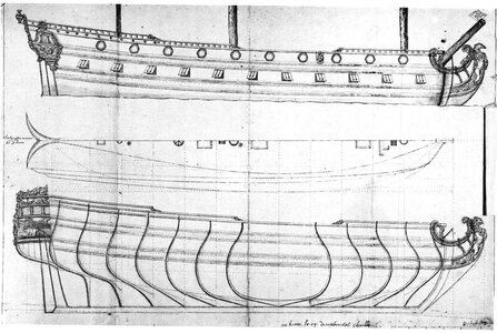

Chaille 1686_sq.jpg

.​
 
Last edited:
.​

The 1686 plan by Chaillé is accompanied by a 'Memorandum' containing the key dimensions of the project in precise numerical form. Comparison of these figures with the plan, as well as the inherent inconsistencies and considerable inaccuracies of the drawing itself, leave no doubt that the plan is not of a working nature that could actually be used verbatim for the construction of the ship, but rather an illustrative sketch, presumably intended for the relevant authorities granting permission to commence construction.

Under these circumstances, the numerical data should be considered decisive, while the sketch itself will serve to extract the necessary supplementary data, although equally important, as only the combination of the two sources of information gives a complete picture of the design.

Transcription and translation of the 'Memorandum' (taken from the monograph):

105 feet of length for the tread of the keel.
25 feet of height to the stem, perpendicular to the lower face of the keel.
9 feet of rake to the stem parallel to the lower face of the keel.
24 feet of height to the post perpendicular to the keel.
3 feet of rake to the post parallel to the keel.
117 feet distance from outside of the stem to outside of post.
30 feet of breadth extreme to inside of plank.
20 feet to the flat of the floor.
13 1/2 feet of depth in hold, measured from the keel to the horizontal line of beam.
20 feet 8 inches of breadth at the wing transom.
4 feet of tumbling home at the midship bend on either side.
2 feet 2 inches of tumbling home aft at the stern frame.
12 feet 6 inches of height of floor at the sternpost.
8 feet 6 inches of height of floor at the stem.
6 feet of headroom between decks amidships.
6 feet 4 inches of headroom between decks aft.
5 feet 10 inches of headroom between decks forward.
6 feet of headroom beneath the quarterdeck.
5 feet 6 inches of headroom beneath the poop.
4 feet 6 inches of height of bulwarks at the gunwale.
13 feet draught of water aft, 10 feet forward when fitted out for sea.


.​
 
.​

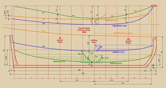
The purpose or nature of the ship to be built and its size, together with its main dimensions, being established, the main design lines (of floor, breadth and sheer), main frame contours, deck lines and major ship equipment followed. If a shipwright with less experience or for a ship of a more innovative nature needed to make a sketch, it would look more or less like the diagram below.

Most of the elements shown here hardly need any comment, except that for the division of the length of the ship into 12 parts, needed for the position of the main and both quarter frames, not the length of the keel or the total length of the hull, but the horizontal length of the line of floor (green line) was taken. This way makes profound sense, as it automatically took into account the rake of both posts, which could vary within quite large limits for ships of different types.

The adoption of specific values for deadrise and length of the floor for all three main design frames (indicated in the diagram), was already sufficient to establish the run of line of the floor of fundamental conceptual importance.


ViewCapture20230715_175908.jpg


Edit:
Despite my heightened vigilance, however, I was caught out by the draughtsman's unintentional or deliberate distortion of the rising line of the floor, if only to hide his professional secrets. This has been corrected by replacing the diagram above.

.​
 
Last edited:
.​
@Hubac’s Historian

Many thanks, Marc. Support needed as this seemingly naive plan is extremely difficult to interpret in detail due to its heavy inaccuracies. I know that you have had l'Architecture Navale 1695 by Dassié for some time. While his proposed design of a ship must be regarded as theoretical, yet it seems Chaillé applied the same geometrical device as Dassié to form the shape of the longitudinal design lines (see Plate 73).

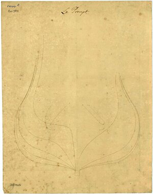
I would also like to show you the body plan (found by Martes in the RMG archives) of the French 68-gun ship La Prompt, built at nearby Dunkirk in 1692 by another French shipwright, Levasseur. Admittedly, the lines on this plan cannot very faithfully represent the original shapes, as they were approximated by the English moulding method, inappropriate in this case, yet overall the preserved shape specifics are strikingly similar to Chaillé's design of 1686 (RMG ZAZ7825 & ZAZ7824).


j6131 - ZAZ7825 - Prompt (captured 1702), plans made 1702,1703.jpg

.​
 
Last edited:
.​

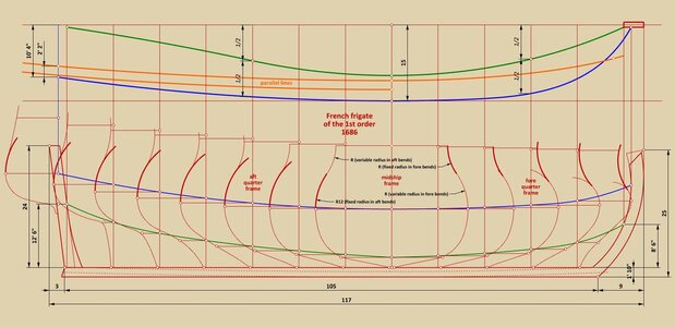
Lower breath sweeps are of variable radius and the diagram below shows a possible way of defining them in a harmonious way and at the same time producing the shape of the frames as drawn on the original plan. The length of these radii is equal to the distance between the two longitudinal blue lines on the plan view.

More telling, however, is the shape of the bottom of all the bends between and including the quarter frames. These are in the form of perfectly straight sections, as would be expected from the bottom-first method described in detail by Witsen.

ViewCapture20230715_215420.jpg

.​
 
Last edited:
.​

It appears that the process of drawing bends was not uniform for all stations, and may even have been subject to local minor adjustments while still in the design stage. It is therefore more convenient to separate this out here, bends at the extremities of the hull first.

The principle shown for drawing these contours should be quite clear, but it may be added that most of the arcs involved had to be arithmetically calculated beforehand, in proportion to the breadth of the corresponding frame.


ViewCapture20230716_112246.jpg

.​
 
.​

Many thanks, Allegheny. I have to admit that in this case I myself am curious about the final results, especially the shape of the waterlines, which may of course emerge at the very end of this venture (in this thread I basically show the progress of the work as it happens, without delay).

* * *​

Now is perhaps the most delicate interpretative phase. Out of several possibilities, I finally chose the variant that seems to me the most logical, and even more important, the one that best fits the original drawing.

The three central bends were given floor sweeps (or maybe better „bilge” sweeps in this context) of the most typical radius, as given in the sources at least for warships, equal to 1/4 the breadth of the hull (tangential to the adjacent lines). For the midship bend, this effectively shortens the "flat" by as much as 1.5 feet on one side, but in practice this translates into only about 1.5 inches of difference measured perpendicular to the contour of the bend. For the other two bends, it is less and much less than one inch.

For the next two bends (i.e. one on either side), there was virtually no choice for perfect geometry but to slightly modify their lower breadth sweep radius.

Finally, the two quarter frames were given tangential arcs as floor sweeps (with very little resulting curvature).

Hollowing curves with a radius equal to the breadth of the hull have been applied to all of these central bends as well, and this basically already defines the shape of the hull in the underwater part.

This is all shown below.


ViewCapture20230716_145927.jpg

.​
 
Last edited:
.​

Oh, if only you had spent more than a few seconds on it, it might have been enough... Although I already accept that decoration, armament, rigging or whatever will always be regarded as more interesting in both the models and the ships themselves :).

* * *​

Anyway, this is the final stage of reconstruction/interpretation of this plan before playing with the 3D model and the waterlines.

The above-water part of the hull is the surface formed by two groups of arcs: upper breadth sweeps and toptimber sweeps. Aft, the upper breadth sweeps have a fixed radius (2/5 x max. breadth) and the toptimber sweeps a variable radius. In the fore section the reverse is true, with the radius of the upper breadth sweeps being 4/5 that of the corresponding lower breadth sweeps. Easy, natural and can be seen below.


ViewCapture20230716_222021.jpg

.​
 
Last edited:
.​

Before going any further...

Did Chaillé indeed use a method as shown here or at least similar? To be honest, it is difficult to be 100% sure of this, as there is still the possibility that he has already applied the method of harmonious division of design diagonals, just spreading in France. The snag is that nothing in his drawing suggests this variant, and its confirmation by graphic means is probably even impossible at all due to the rather coarse inaccuracies of the drawing.

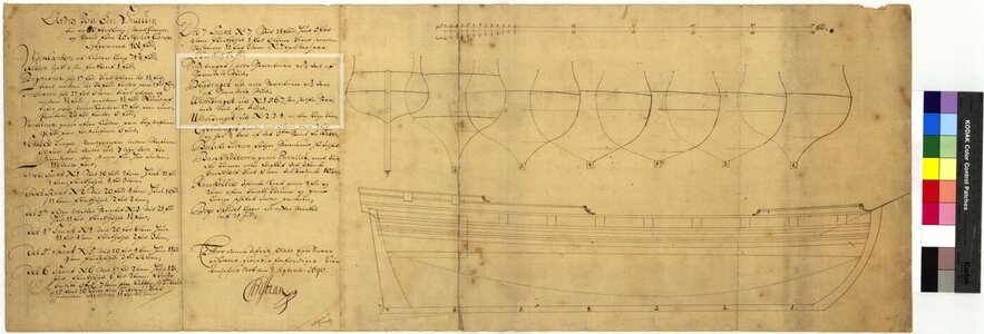
In this context, it will not be out of place to show at least one of a fairly large group of Danish designs from the late 17th and early 18th centuries, specifically of the ship Maagen of 1690, approved by none other than the sovereign himself (again, found by Martes in the Danish archives).

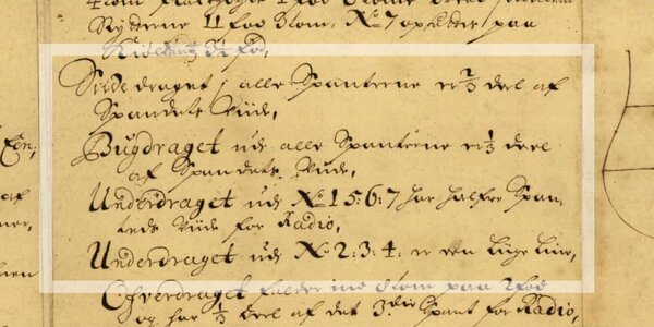
As a whole, this series of draughts is extremely detailed, and everything on them is à la hollandaise (or more precisely: as we know it from Dutch works on shipbuilding), that is, from general shapes down to the smallest structural details. Especially the legend on the attached here plan A-259-I may be regarded as essential, as it effectively reveal the most important things to the designer, both in the design process itself and in terms of the results obtained from that process. Of particular interest from the point of view of design concept is the passage that reads as follows:

[...]
Breadth sweep in all frames is 2/3 of the frame width,
Floor (bilge) sweep in all frames is 1/3 of the frame width,
Hollowing sweep radius of [frames] No 1, 5, 6, 7 is equal to each respective frame's width,
Hollowing sweep of [frames] No 2, 3, 4 is a straight line [...].


Many, if not all, ships of this group are conceived in the same way.


A 259 I - Magen 1691 - aaa.jpg


A 259 I - Magen 1691 - bbb.jpg

.​
 
Last edited:
.​

The method on the draught of 1690 shown above must have been efficient enough and attractively simple at the same time, although, as is to be expected from such rather mechanical transformations of respective frame widths, it could not generate perfectly smooth surfaces. However, the approximation of the desired shapes must have been sufficient. Or, in other words, it was just enough to not design something that could not be evened out with battens and dubbing during the actual construction of the ship.

This is perfectly illustrated by one of the last plans of the series, conceived using the same method and by the same designer, Ole Judichær, only made 36 years later (Danish archives A-956). This time the designer corrected the contours of the frames already at the design stage, using the design waterlines (although at least corrective diagonals would be already expected at this rather late date), and the extent of these corrections can be seen very well in the reproductions of this plan attached here.


A956.jpg

A956 - Copy.jpg

A956 - Copy (2).jpg

.​
 
Last edited:
.​

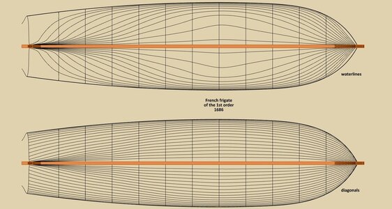
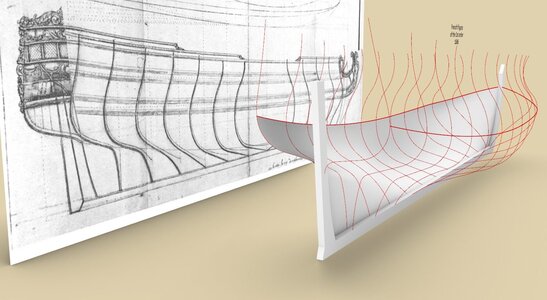
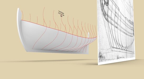
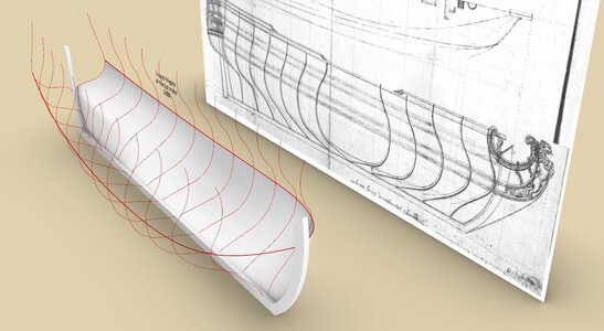
Back to the Chaillé's design. The resulting shape is not overly ideal in terms of surface regularity (but perhaps acceptable by the standards of the era), as there is a slight concavity between the central and aft sections, which by the way would have been easy to fix, now and then. However, I decided not to correct the source, showing the lines as they come out according to the original draught.

Had the ship been designed on a diagonal basis, the resulting lines would probably have been better in this respect, assuming, of course, that the drawing was accurately executed.

Thank you,
Waldemar Gurgul


ViewCapture20230719_180116.jpg


ViewCapture20230719_181616.jpg

ViewCapture20230719_182309.jpg

ViewCapture20230719_182339.jpg

.​
 
Last edited:
Back
Top