English 6th rate ship – reverse engineering the draught from the late 17th century

Joined
Apr 26, 2023
Messages
383
Points
323

Location
European Union
.​

Among the generally quite few early modern plans of ships of technical nature, there is another one, tentatively dated to the late 17th century. This draught, of unknown authorship, must be one of the very first depicting frame outlines in a fairly precise manner, and in this respect it may be considered a complete design. It depicts a rather modest vessel, which Brian Lavery identifies as an 18-gun ship of the 6th rate of c. 1670 (see B. Lavery, Deane's Doctrine of Naval Architecture, 1670). It is part of the RMG collection, with inventory number ZAZ4602 (J0052).

With some knowledge of the design techniques of the period already in hand, it is worth taking a closer look at this particular plan as well, in terms of the conceptual methods employed, which will perhaps allow it to be more accurately positioned chronologically, and perhaps additionally uncover some previously unknown design details.

After a preliminary assessment of this plan, it must also be acknowledged (especially after a recent experience with Keltridge's drawings of 1684), that this plan was certainly executed by a professional draughtsman and, for the possibilities of the manual drawing method, appears as the apotheosis of quantum precision.
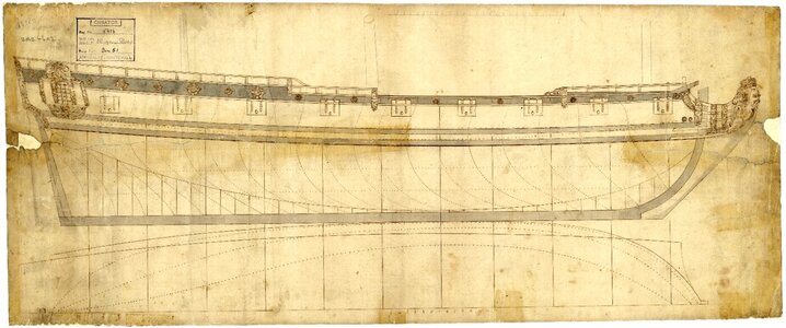

Unknown 18-gun Sloop (no date) RMG J0052 (1600x673).jpg

.​
 
Last edited:
.​

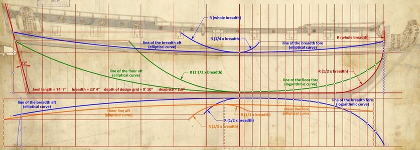
Looking at the diagram below, one almost gets the impression that it is one of the sketches taken from Sutherland's The Shipbuilders Assistant of 1711. Most of the main design lines are the elliptical curves he describes. In addition, there are two occurrences of the logarithmic curve, one for the narrowing line of the breadth fore, and the other for the rising line of the floor fore. The first known and dated occurrence of the logarithmic curve on plans of English origin is found in drawings made by William Keltridge in 1684. Not a single arc of a circle, except those applied to the stempost.


ViewCapture20230626_174658.jpg

.​
 
Last edited:
.​

@Ab Hoving

It's nice of you to look here, Ab. I'll take this opportunity to say that I find the resistance of Dutch shipwrights in the early 18th century to adopting 'transverse' English design methods increasingly understandable and justifiable. Even in England itself they caused political ferment some time later, and the consequent copying of French designs on a massive scale.

.​
 
Hi Waldemar,
I follow your remarkable projects with great interest, especially because the geometrical exercises you describe go way beyond me. I praise my luck that Dutch shipbuilders never went into such extreme design methods. Personally I think that the method the shipbuilder Paulus van Zwijndregt (1681-1749) from Rotterdam developed in the first quarter of the 18th century is much more elegant and practical than all this British magic with sweeps and logarithmic curves.
I admire your knowledge and skills.
Ab
 
.​

@Ab Hoving

Many thanks, Ab. As it happens, even eminent historians or experts with a direct interest in this period and place have become lost in these geometric constructions of the highest finesse. :)

By the way, I noticed that the issue of Dutch ship drawings is surfacing again. Yes, it's about those 17th century drawings made by a shipbuilding dilettante (but a great illustrator and painter), commissioned or assisted by a graphics dilettante (but a professional shipwright). Resulting in great, visually very attractive advertising material of some 17th century shipyard or shipwright, and also suitable for eventual publication, as – for example – in Witsen's monumental work. So you can't complain about the lack of problems in interpreting them either, requiring, after all, the highest levels of skill and knowledge, like yours. :)

.​
 
Last edited:
.​

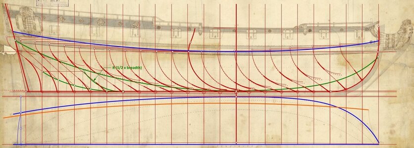
In order to get the contours of the frames in the aft section, the auxiliary line not drawn on the original drawing had also to be reconstructed beforehand. In the attached diagram this line is green, and it is also an elliptical curve like most of the other main design lines.

The rising line of the floor (also in green) was not used at all to plot the frame contours, but it may have been useful at the preliminary stage, to approximate or check the dimensional parameters of the design.


ViewCapture20230628_120008.jpg

.​
 
Last edited:
.​

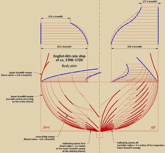
The diagram below shows the reconstructed method of drawing the frame contours (as a body plan of the ship). If it were not for some differences, it could be said to be lifted alive from William Sutherland's The Ship-builders Assistant of 1711. Or even that the design of this ship is even a little more sophisticated, especially through the use of logarithmic curves, design waterlines and more sophisticated geometric devices to reduce the radii of the breadth sweeps.

Overall, when considering the design features of this plan, they seem to point to 1700–1720 as the approximate time of its creation.

Thanks again for following,
Waldemar Gurgul


ViewCapture20230628_131111.jpg

.​
 
Last edited:
Overall, when considering the design features of this plan, they seem to point to 1700–1720 as the approximate time of its creation.

The deep and heavy head seems to concur with this assessment, but the overall style of the plan is somewhat archaic for the time.
On the other hand, the plan is definitely a presentation piece, so the styling may have been intentional.
 
Last edited:
@Waldemar I am in awe of your skill set and knowledge of ship design (overall) and of this specific period. Your work is simply amazing.

Thanks a lot, Allegheny, but it's really not about unconditional affirmation or another birthday wish. Rather, I would prefer a thematic exchange of findings or specific, constructive criticism. So far to no avail, if you leave out the invocation of giants and some fires in the archives (as in another forum). But if such stories suit someone better, I can't help it....
 
Last edited:
Back
Top