Attaching metal plates to ship's hull

Joined
Feb 22, 2020
Messages
283
Points
168

Location
Ennismore, Ontario
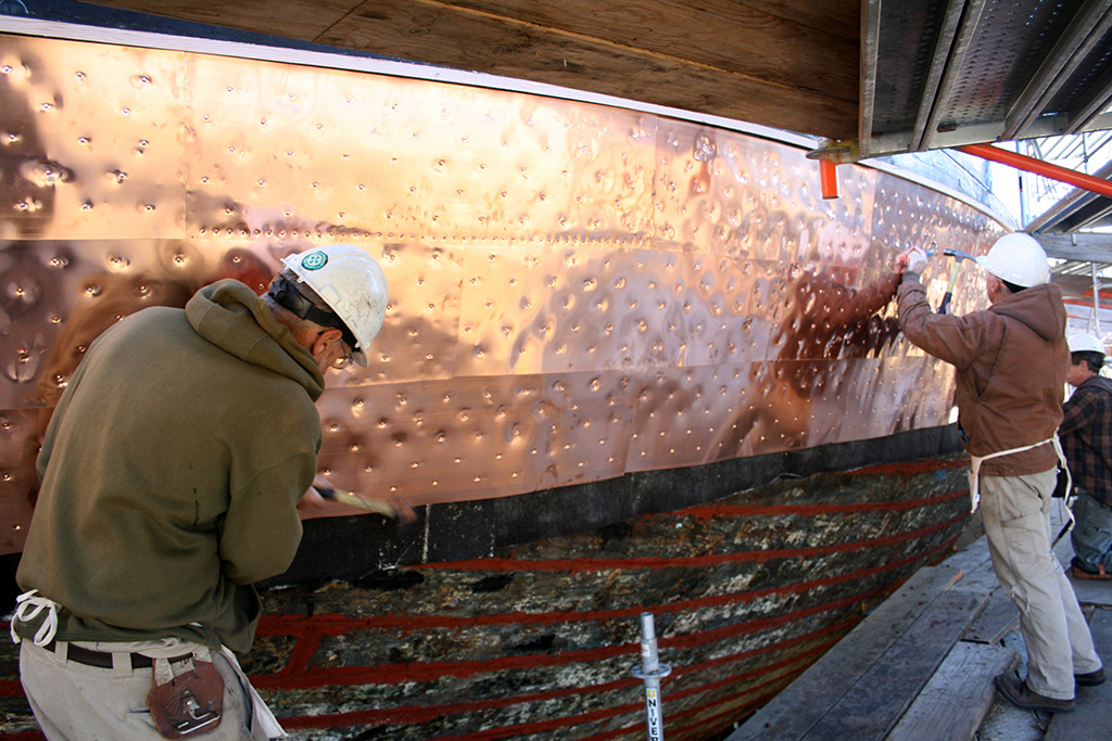
HMS Terror, of mid-19th century polar exploration fame, had iron plates installed at the bow from keel to well above the water line. Reference books say they were riveted on. How could they be actually "riveted"? In other construction, to rivet two 3/8" thick plates together normally, you would have two precisely located holes lining up in each plate, put a red hot rivet through the hole from one side and use an impact tool of some kind to "mushroom" the exposed head, while someone holds a heavy anvil like tool at the end that already has a head on it, to keep it in place and make a tight joint. When the rivet cools, it gets even tighter. But on a wooden ship, you can't access the side against the wood obviously. So how did this work? Were they actually more like lag bolts that drove or screwed into the wood of the hull? Copper sheathing was attached on other ships but I think that apples and oranges. Copper is soft and was more like sheet and could be nailed on???
 
Last edited:
A very interesting and educational read


For our German-speaking community (attached)
Yes, coincidentally I read that earlier tonight. It's a bit confusing as to why the copper bolts should be the source of galvanic corrosion versus the iron hull bolts, rather than the huge surface area of raw copper sheathing material. I think something is awry there, but it doesn't help me with the iron plate questions. It's hard for me to believe that they would drill through-holes foe bolts for the sheathing, so it likely must have been lag bolts -- big screws basically. Some interesting images on USS.Constitution...
 
Do you have a book for HMS Terror? I wonder if the book mentioned anything about the steel plates and bolting. I will look further today...
I do. I have Matthew Betts's excellent book. That is part of the confusion. They are referred to here and there as being "riveted" in place. Matthew Betts, in his book "HMS Terror", shows them as having a row of rivets all the way around the perimeter of each plate in the external hull side elevation dwg on pg. 135. That would imply that they didn't overlap. But the details of the application of the brass plates on his model as in Figs on pp 184 and 185 show them apparently overlapped and with each plate having rivets simulated on only two edges, as they would look if overlapped and riveted in typical platework style. And they overlap from bottom to top and from aft to bow, like shingles on a roof (the upper and most forward plates being topmost.
Q: which is it? I can make an argument for both designs having advantages. Overlap seems more structurally strong as you have fewer exposed edges for the ice to get at, but on the other hand, each seam has a raised edge and requires several precisely matching holes in the edges of multiple plates (each plate shares edge holes with at least 4 others -- maybe 8 if you count the corners). That is some challenging iron work for 1845?
Here I found more information. The first PDF document you can start reading it from page 27 onward. The document is worth reading as a whole, but from page 27 it discusses The techniques of Methal Sheathing.
 

Attachments

  • The_Introduction_and_Use_of_Copper_Sheat.pdf
    2 MB · Views: 18
  • 2012_Chapter_34_Use_of_Pine_Sheathing_o - Copy.pdf
    1.9 MB · Views: 12
  • 2015_The_Use_of_Copper_and_Lead_Sheathi.pdf
    1.2 MB · Views: 12
  • Copper_and_other_sheathing_in_the_Royal.pdf
    647.6 KB · Views: 11
I'll certainly read this but I've figured this much out: copper sheathing was sheet material weighing 12 to 28 Oz (say 340 to 794g) per square foot (about 625 sq cm). Iron was plate material and weighted say 20 times that amount. Copper sheathing was nailed. Iron plates on Terror and Erebus needed something more robust.
 
Last edited:
Back
Top