ROYAL CAROLINE 1:30 by Zhl my version, by Peglegreg

So finally the start is done. Wish you a good journey......I will follow and thanks for sharing

Thank you Uwek,
I've been working on the design aspect for a long time now, the keel and all the bulkheads, as well has the plans, have all been scanned and
I'll post some of the results of the design soon.
20180122_170256.jpg
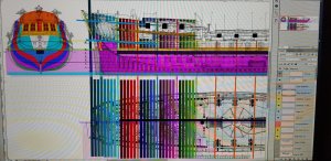
At the moment, what you will see on the screen will be a mass of colours and shapes. You can say that the screen is my 'shorthand' and only I can make sense of it. But I'll do some basic drawings so 'Joe the public' will understand what I am endeavouring to do.
Havagooday
 
Hi Greg,

I didn't knew the chair doctor glue and briefly checked and it even seems to be available in the EU. Normally I always use UHU Hard for these tasks but the capillary and filling function of this glue sounds very interesting. I will order one. Thx for the tip.

Regs Maarten
 
Hi Greg,

I didn't knew the chair doctor glue and briefly checked and it even seems to be available in the EU. Normally I always use UHU Hard for these tasks but the capillary and filling function of this glue sounds very interesting. I will order one. Thx for the tip.

Regs Maarten

G'day Maarten
The glue is great and very strong. I am using the keel, moving it, putting on and removing the bulkheads for a long time, while I was working on the design and I haven't used the strengthening pieces supplied for the keel from the kit, because I'll be doing something different. The keel is still 'straight as an arrow'.
The glue is quite expensive though, but it's worth the price and only use it when you are doing 'dry-mounted gluing'.
I've got it from a place in Australia - timbecon.com.au but you can also get it from America.
I think there a new phrase, that we all could be using in the future 'dry-mounted gluing'.
havagooday my friend
Greg
 
John: Can you explain your technique for rope making? What thread do you use? When do you dye- before or after laying up the rope? What brand and color dye? Etc.?


G'day Dave,
I will try and post something in the next week,

best regards John.
 
Hi Greg,

Dry mounted glueing sounds like rocket science and for sure will have the future. :)

By the way I bought a rope serving machine and a small roping makchine from Domanoffs Workshop (inspired by Arthur with his great Vanguard) and will use it to start rigging my "Friesland" and think I will start a new log on that one in the near future.
So John all tips are welcome.

regards Maarten

G'day Maarten
Could you post a link for the ropewalker and server machine please?
It would good to see a log on these machine so everyone can put place theirs verion, to show the difference etc.
Havagooday
Greg
 
The Stand Part 1
G'day all

I would assume that this build would take me at least 5 to 6 years to complete, so the week or so that I'm working on this multi purpose stand will not be wasted.
Many of you may already know that I have Parkinson's Disease, I'm very slow, and it makes me very frustrated, because I can't work as fast as I could before PD. So I will warn you all, this build is going to be slow. Having PD will NOT beat me, and I have and always find a way to counteract the shaking in my right hand, by 'Thinking Out of The Square'. but as I have said before, I'm very slow.
Having PD is the main reason why I'm going through this trouble to construct this stand. The only time the Royal Caroline model will be off this stand is when it will be finally placed into the display case. My motto is 'better be safe than sorry'.

The design
The way I have designed this stand, is to have a swing platform that will hold the model via the keel using 12mm Hight Tensile Bolts. The same bolts will be used to attached the finished model in the display case.
This swinging base, can rotated to work on the model upside down or at 45 degrees sections. This will help me a lot in the progress of the build. I don't trust myself to handle this large model without doing some minor or major damage to it, if I did not have this stand.
NOTE: I will be using this swing base to help me balance the weight difference from the port and starboard sides when the merbau forms are added. (See previous post).

The base.
The first thing you will notice about the wood that I used, has old screw holes. All the timber that was used in this stand (and also the extra forms used in the model) are being recycled from an old step that I made for my late father, so he could step down on a large platform.
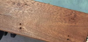
screw holes.jpg
45mm and 75mm screws were used to join the pine timber to the merbau timbers side. A 5mm deep slot was cut inside and around the four sides to place the 7mm thick plywood base. This formed a a shelf under the model, so I'll be using it, to hold all of my gadgets and tools while I'll be working on the model.
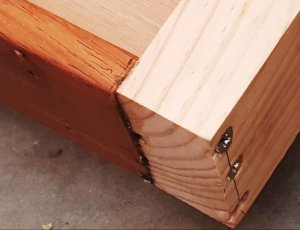
corner of base.jpg
Below is the shelf that was slotted in the 4 sides by 5mm
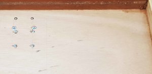
Ply slot.jpg
A rebate was cut in the middle of each small sides to hold the vertical post
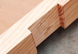
Rebate Slot.jpg
Under the shelf, three timbers were used to help hold the base and straighten it all the pieces together. On the two merbau stenghterners was placed the four casters.
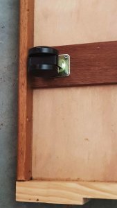
Casters.jpg

The post
The two vertical post has each have a swinging arms, which I mentioned earlier. On the base of these swinging arms will be placed the bar that will have the 2 anchor bolts will be connected to the keel. The massive nuts will be incorporated into the keel and the the bolts will be removable.
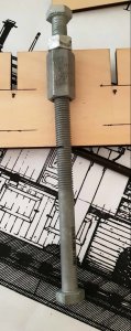
Nut and Bolt.jpg
The locking mechanism that I was planning to use didn't work as I have planned. MY FIRST BOO-BOO IN THE BUILD! What I was planning was to file a 'V' shape on both of the protruding spacers.
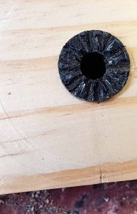
Final File Result.jpg
In theory the 'v' sections on both the vertical and swing arm. should be intertwine to each side to hold the model at different angles. It worked, but it wasn't strong enough to hold any weight. So I decided to but a bolt through the outer vertical post and be anchored to holes in the swinging arms. A piece of merbau timber was placed on each of these arms for the 'wear and tear' that would invariably occur, with constant use. This is far superior than just using pine!
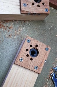
PIN holes Method.jpg
These brass bolts are screwed into the vertical post using the hidden nuts and the end of the bolts will go into the holes in the swinging arms.
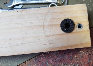
Hdden Nut.jpg
Post on left shows the brass bolt extending out. while the post on the right has the bolt protruding in the swining arm
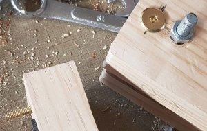
LOckig pin  Main.jpg
The nut on the vertical post
Hdden Nut.jpg
This worked at last, but, alas, I was out by about 3 degrees.as you can see in the next photo. My second boo-boo. There will be more boo-boos to come, I assure you of that!
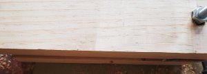
Angle out.jpg
I have to work out what I can do about this problem...... hmmmm think, think, think
See part two: The Conclusion of the Stand Build.

Thanks for watching and happymodeling to all.
Greg
 
Hi Greg,

Nice to see all these steps before the actual build. Sure you will find an excellent solution and the result will be an amazing rig.
PS it is not about speed but fun. My project will take time also, I do have ample time to work on it.

Keep up the good work

regs maarten
 
Hi Greg,

Nice to see all these steps before the actual build. Sure you will find an excellent solution and the result will be an amazing rig.
PS it is not about speed but fun. My project will take time also, I do have ample time to work on it.

Keep up the good work

regs maarten

Thanks Maarten for your vote of confidence.
There's a saying in Australia: ' there's more than one way to skin a cat'. I'm sure I will work out any problems now, or when I'll come to it.
Havagooday my friend
Greg
 
G'day all
Luz and I would like to say to all the Ozzies out there:
A very happy and a safe
AUSTRALIA DAY.
God bless our beautiful country and it's multifold of people, who are now proud Australians.
Havagooday to all
Greg
 
G'day everyone
This week has been very bad for me. As you all should know by now, I've Parkinson's disease, but recently I've been diagnosed with crohn's disease. Now, the problem is, my body is not absorbing my PD medications as it should, because of crohn's, so I've been having FULL BLOWN ATTACKS OF PARKINSON'S.
These attacks last up to 3 hours before I calm down to to a point I've got some control over my arms, legs and head, but it can be 3 to 4 days until I'm back to my usual self.
I'm am not telling you all this for pitty, but to explain what I've decided to do. If I've learnt one thing from this, may be some time in the future, that might be my permanent state. Hopefully I've got years until that happen.
So you will find my building log very disjointed, because I'm going to do all the fine 'motor skills' first and put them into a Chinese container with packing, for when I'll need them.
So here we are now.
The first thing I decided to do was to prepare all the carvings.
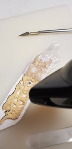
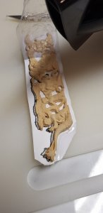
Taking the plastic off these 'well packed' carvings was to remove the sticky heat shrink from them. It was a very tedious and nerve wracking job. I have to be careful not to break any of the very fine thin pieces.
Then I had the brainwave of using a hair dryer on the cut-out pieces and slowly bit by bit the plastic melted enough to 'lift' off the wood without any effort.
20180131_175110.jpg
20180131_175145.jpg
I have to work in about 20mm sections at a time, but it worked great.
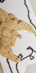
20180131_175247.jpg
Even the tiny horn, the heat shrink lifted off with ease.
Thanks for watching and havagooday
Greg
 
G'day all
I havta to say a huge thank you to two of my great mates and fellow RC builders, John and Maarten.
Following what they said in there logs etc. I have decided to add a further 15mm in the lenght of the false keel. John has pointed this out to me, and it's a VERY GOOD POINT. Both John and Maarten have to some 'surgical' work on their carvings to make them fit.
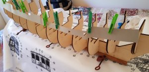
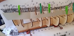
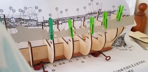
By laying the cardboard template over my dry fitted bulkheads, the template fits perfectly.
20180207_150350.jpg
20180207_145731.jpg
20180207_161624.jpg

The template fit perfectly with the model.
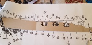
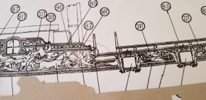
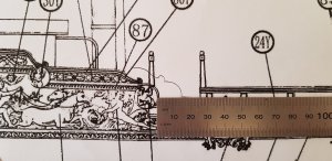
BUT THE PROBLEM IS: the template don't fit the drawings of the carvings which has been expanded lenght wise to compensate for the 'curved effect' from a 2D to 3D model.
John told me that the carvings fits perfectly on these drawings, because he said this, I didn't have to check myself. So...
20180207_151050.jpg
20180207_170419.jpg
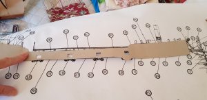
So putting the cardboard template over the drawings, my finger is pointing to the 'error point'.
20180207_151100.jpg
As you can see the template is longer at this point and it's 15mm as per my ruler.
20180207_152117.jpg
So, all I have to do is to expand the false keel by 15mm.
I have decided to spread is distance between bulkheads 5/6. 6/7 and 7/8, this is the flattest area of the Hull. 5mm for each these areas, and the 15mm will be added on the deck between the main and fore masks.
Using my hard wood strengthening method and by putting a solid hardwood keel made up of Tasmania oak which is very close to the colour of the planking.
This keel will have a 6mm slot cut into it, so the false keel can slot into it. The keel it will be12mm at the widest. This will help to make the false keel straight. So I have to carve the keel from 8mm at the bow and stern post to 12mm at the midship. the stern post will be wedge from the top of 10mm to the keel where it will be 8mm.
The bow stern post will have a double wedge, at the hull outwards near the bowsprit will be 12mm to the outer edge of 8mm. the vertical bow post will be (near the hull) will be decreasing towards the keel from 12mm to 8mm at the keel. the forward edge of the bow post will be 8mm from bowsprit to the keel. Doing this, the bow and keel should look more authentic in appearance.
Again thank you Maarten and especially to John, whom was so informative with the solution to where and how much I should extend the false keel and the keel.
Happymodeling to all and thanks for watching.
Greg
 
Last edited:
G'day Greg, you wrote the following,

the template don't fit the drawings of the carvings which has been expanded lenght wise to compensate for the 'curved effect' from a 2D to 3D model.,

where did you get that info from, the drawings of the port and starboard side drawings havn't been expanded, maybe I missed something,

best regards John.

G'day John
This is only my assumption, because it makes sense to me. I laid the carvings over my dry mounted bulkheads and I got a very similar, to a degree as what I would expect. The lenght is about 15mm longer a per the template.
That is the only reason why I havta extend the false keel to compensate for the over extended drawings.
Hope this explained my assumptions to you and everyone else.
Havagooday mate
Greg
 
G'day Greg. If that is an expansion drawing the whole side of the ship would be flattened,
Best regards John
 
G'day John
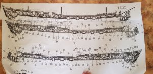
I've just printed and joined the drawing of the carvings that you showed me yesterday. This is the exact size of my kit and my drawing of the kit.
You see in the pic below the template over my new printout. The lenght is the same.
20180208_124226.jpg
This pic is my printout over the carvings drawing. It's 17mm shorter than the carving's drawing.
20180208_124451.jpg
So there fore, I have to expand the false keel to an extra 15 or 17mm to compensate for the carvings being too wide.
I'll ring you soon mate
Allthebest
Greg
 
Back
Top