ROYAL CAROLINE 1:30 by Zhl my version, by Peglegreg

G'day everyone.
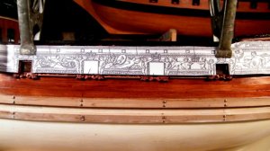
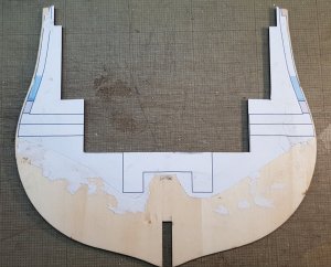
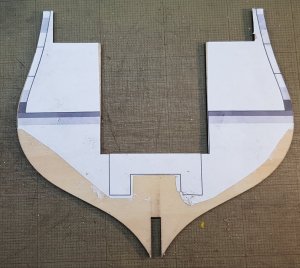
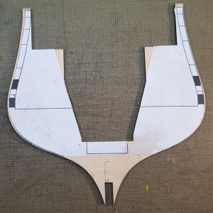
When I'm up to this stage, before cutting out the windows and gun ports, I'm going to do Maarten's idea and place all the dry mounted carvings on the hull and mark where the ports and widows should be in retrospective to the carvings.
There will be a slight movement from the actual yacht because of the expanded carvings. It will be close, and hopefully only you guys will know they are in the wrong position. I doubt anyone would notice, even the experts because they be out to a maximum of 5mm. Anyway the yacht is longer, so it will not be a true representation of the RC.
Thanks for watching
Havagooday
Greg
 
Hi Greg,

Clear pictures showing the differences, where is the top shorter drawing coming from?
I don't think there are still original drawings or a dockyard model from this vessel so we dont know what the actual vessel exactly looked like. This means all our interpretations are as close as possible.
I think your solution is the best.

Regs Maarten
 
G'day Maarten
Thanks for your vote of confidence. Thanks to John and his advice and phone call, he pointed out an error in my original log. I named the sections of the extension from aft of bulkhead 7. In actual fact it should be forward from that bulkhead. That is what I was planning to do, but I made a boo boo in my writing. It's now corrected!
:eek:

I havta say again a huge thanks for John to how to do the keel and die and stern post correctly. His information is our gold.
Havagooday mate
Greg
 
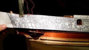
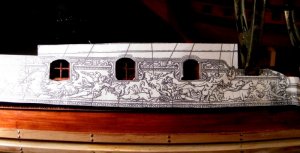
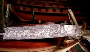
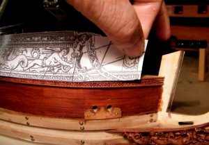
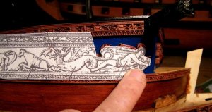
G'day Greg, I have done what you wanted and stretched a piece of string around the model and then placed it over the AOTship drawing, but the string was too stretchy so I cut the plan and placed that over the model see attached pics,


1.jpg
I started at the stern, I put the drawing over the hull after cutting out the windows, so it is sitting over the windows
and the side gallery, you can see it is overhanging the transom.


2.jpg
Sitting over the side windows just nicely


3.jpg
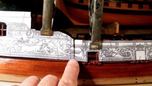
now we get to the spot where something has gone wrong, I've folded the drawing back under itself so the fourth
port is in the right place.


10.jpg
with the drawing unfolded you can see the difference


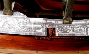
4.jpg
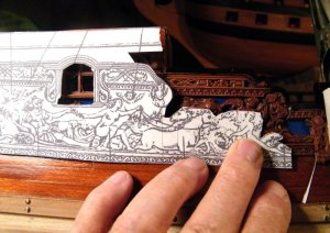
after I had done all the measurements with out cutting the drawing, I then went back and cut the drawing,
trimming around the horses and figures so you can see that it is correct at that spot


5.jpg
this shows the drawing sitting correctly over the four gun ports


6.jpg
now this shows the drawing held out flat from the model, I have clamped a square to the stem where the decorative
rail would finish and you can see that the drawing is longer when held out flat from the model


7.jpg
However when I tried to take the drawing round the bow to meet the stem, which if it was a expansion drawing
it should have, it was too short as you can see


8.jpg
again I trimmed the drawing so you could see that it corresponds with the carvings in that spot


I do not think this is an expansion length wise, I think maybe someone developed the kit of the hull and someone else developed the drawings not realizing that the scale was slightly larger, and then when they have realized what has happened they have come up with the template to get the carvings in as best they could,

best regards John.
 
Last edited:
Hi Greg,

Clear pictures showing the differences, where is the top shorter drawing coming from?
I don't think there are still original drawings or a dockyard model from this vessel so we dont know what the actual vessel exactly looked like. This means all our interpretations are as close as possible.
I think your solution is the best.

Regs Maarten


G'day Maarten and Greg, I found the plate online, I remembered that a man called Chapman had something to do with designing the Royal Caroline, so I googled and came up with the info, if you have the book AOTship The Royal Caroline, go to the page Resources used to develop the ship and there they tell you that there are three lots of plans, some they got from the Maritime Museum in England and the one with the decorations is by Chapman,

best regards John.
 
G'day John
What ever happened is in the pass now, all I have to do is to correct the mistake by doing what we've talked about.
I think any future RC builders, would have learnt a lot from this, yours and Maarten's build logs and they will be aware of any problems.
Taking this into count, I still think this is still one of the best kits on the market. I'm so glad that I have it and I'm sure any future RC builders will think the same.
Thank you John for all your input in correcting my build. This is one example why you are a true friend, not only to me but for everyone.
Havagooday tomorrow mate
Greg
 
The Keel Stands
This will be in inner 'guts' and strength of the keel stands.
20180215_071830.jpg
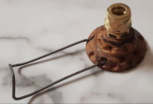
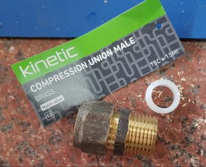
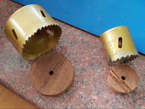
You will notice that the core is a brass water pipe connector, the internal hole in this connector is 12mm and the bolts fits 'snuggling' inside. These brass fitting is screwed into the merbau round base.
The discs are 10mm x 64mm diameter and the base is 16mm x 44 diameter for the upper neck where the brace fitting will be attached.
20180215_072311.jpg
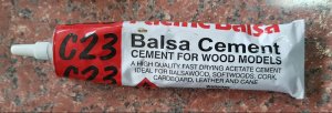
The next step was to glue the 2 pieces of merbau together. The choice glue for spread and strength was balsa glue.
20180215_072550.jpg
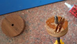
Before glueing the two pieces together, a Philips Head screw driver were place into the hole so both of them will be in-lined.
20180215_073259.jpg
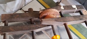
The discs were then clamped for half an hour for a extra strong bond. Normally the glue is bonded enough, after 5 minutes.
20180215_072816.jpg
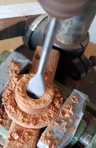
A 18mm auger bit was used to drill the hole in both the merbau discs.
20180215_073548.jpg
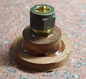
The discs were tapped and the brass support were screwed into the merbau base.
For extra strength, an epoxy glue was used to permanently join the brass in place and the epoxy glue was placed along the edges of the two merbau pieces.
20180215_073745.jpg
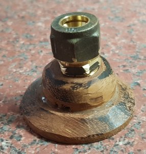
The edges of the disc was sanded to a rough angle. This would be easier to do before the brass support was glued in, but alas, it's was my boo-boo!
20180215_074602.jpg
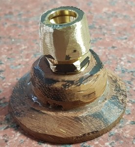
The next step was to removed the octagonal sides
of the brass support. This was a simple process by using a bench grinder.
20180215_074743.jpg
For extra support for the clay, slots were ground into the edges of the brass so the clay will bind into each of the crevices.
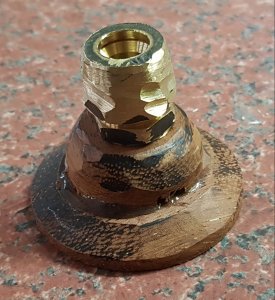
20180215_075430.jpg
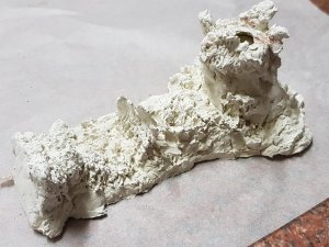
The final step was to make the merbau base rougher so the clay will have something to cling to. Also on one of the stands there will be an extension for the carved name plate stand. A old wire cloths hanger was used as a support for the clay.
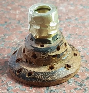
20180215_075340.jpg
20180215_075806.jpg
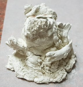
The clay was placed and molded over the stands.
I used an air dried clay over the over type because.........
I was afraid the brass could crack the outer clay shell If it was placed on an oven.
I have used this air-dried clay before and the results were quite good. The clay can be carved to get a finer detail after the drying process has been completed. The only drawback is that it's not structurally strong, but the brass will be the inner strength, and I'm not worried.
I hope that you can all are what I was trying to obtain in these 'sculptures'. If you can't, it supposed to be a coral reef display. o_O
20180215_080158.jpg
20180215_080228.jpg
This photo shows a 15mm timber which represents the keel and the carved name plate in a rough position.
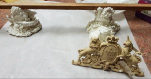
20180215_080620.jpg
This is where I would
like some

In-put from you all!

I was planning to sprayed the whole keel stands black and then I painted gold over the black to get (hopfully) an aged gold look.
But I was thinking today.....
..........I might paint the reef scheme in their natural colours. This way the coral, sand, rocks and the eel will be quite colourful.
Also the what should I do with the name CARVING. Gold or paint it with different colours?
What do you all think, of these ideas of finishing: gold effect or colours of the reef?

Hmmmm I don't know which would look the best.

So PLEASE help me!

Thanks for watching and happymodeling to all.
Greg
 
The base supports look good Greg. I think if you were to paint them gold it might take something away from the actual ship which has a lot of gold on it. How about using coral coloured paint, just a thought,

Cheers Andy
 
The base supports look good Greg. I think if you were to paint them gold it might take something away from the actual ship which has a lot of gold on it. How about using coral coloured paint, just a thought,

Cheers Andy

G'day Andy
Thank you for your opinion, and I'm starting to agree with you.
o_O
I think, I might also try to do some simple wooden turned posts. I've got the wood lathe tools to do the turning of the post BUT. I don't have a lathe.
:eek:
I'm going to try to turn them using my drill press some how......
Will do another post if it works.
Havagooday mate
Greg
 
Hi Greg,

Just thinking out loud. Go to the local furniture recycling store and find an old cheap rocking chair with turned wood. Cut out the parts you like drill them out to fit in your supports.
No lathe needed.
 
G'day Maarten
Thank you for responding to my call for assistance. I really appreciate your time in doing so.
That's is what I'm going to do. I had a survey among friends today and they all think GOLD is out and PAINTING is in.
I'll will do it that way, but I think it's might be a big chunky as a keel stand.
I've been working on a way today to turn my drill press into a vertical wood lathe.
:p
I done a test run on some scrap and it works well in small areas. The test will be, if I can get both stands uniform.
I'll post an update of the painting and also the turned stand in a few days.
So I'll have to choose from the plain stand or a coral reef. As John told me, you don't want people to look at the stand rather than the model!
:rolleyes:
I joined 2 pieces of 20mm thick Tasmanian oak today and the wood is in 2 clamps and a vice for 24 hours.
Then Mark II will begin.stay turned for another update in a few days.
Thanks for watching
Greg
 
Hi Greg,

Just thinking out loud. Go to the local furniture recycling store and find an old cheap rocking chair with turned wood. Cut out the parts you like drill them out to fit in your supports.
No lathe needed.

G'day again Maarten
I was thinking of something similar, but I'm to go to our local hardware shop and look at fancy turned timber in the federation building supply department.
Have a great two-week skiing mate.
Greg
 
Ureaka!
At Last

PART I

G'day all memattie
It's hard to believe that just over three months of working out and redrawing this kit, I have come to a conclusion............
Now wait for it....................
I HAVE FINISHED and I pray that there wouldn't be any hick-ups. If that happens, it would be the first for me. With my experience, there are always unforseen obstacles that will but up it's ugly heads. This is why this hobby is so fun, isn't it?.... Trying to work out what to do next!


So, as Brian would have put it,
It's dust time. Hip, hip hoary!
This is my plans (So far), with the great help and encouragement of both John-Neptune and Maarten, I'm going extended the lenght of the false keel by 15 mm.
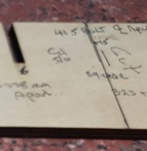
The photo below shows a pencil line and that is where the extra 15 mm will be added between BH5 and BH6.

20180324_015147.jpg
John mentioned to me on one of our numerous phone calls he said, "Hindsight is a wonderful thing, if he knew then, what he knows now, I would have extended the keel myself". He was referring about the placement of the carvings and he knew it would be easier to place them if there were more space available on the port and starboard sides.
:D
He was giving me all of his knowledge of his build, and he said the tightest area for the cravings, were detween the main cabin and before the first gun port. Luckily this are is where these is 'no curves' in the hull.
:oops:
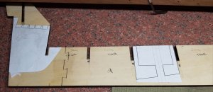
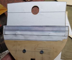
The next two photos are the drawings that I will be using to place the bolts. The odd shape is best to be explained in the next (FULL) post. Sufficient to say, it has a big issue of putting the 5 volts DC into the model via the two bolts.
:eek:

20180324_015010.jpg
please note the keel will also be cut at the stern to allow for extra forms to be placed using the zig-zag shape at there
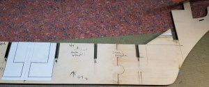
20180324_014943.jpg
also more there is a small piece that will be cut of the false keel at the bow - it's a small horizontal section just after the first bulkhead


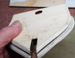
The following 2 photos are samples of the beveled edges on the bulkheads.
20180324_015059.jpg
20180322_184111.jpg
I left some 'meat' on them purposely because after all of them are placed and glued on the keel, I will make a final sanding with a sandpaper wrapped over a piece of wood. Hopefully the result would be smoother.

;)
When talking to John, he mentioned that these lines are very accurate. This method of what I'm doing doesn't mean I don't believe John, but I have to make sure that the extra lenght in the hull wouldn't be any detriment to the predetermined kit's final shape.

More to come in PART II

Thanks for watching and happymodeling to all
Greg
 
Hi greg, good to see it is dust time.
I think you already deserve a reward for starting to create dust and already have 6 pages in your blog.
I love your blog with all your thoughts and well layed out approuch to this build. I will be sitting front row, if there is still a spot free, for your great conversion of this kit. Lots of fun.

Regs Maarten
 

PART II
G'day all memattie
Continuing on....
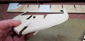
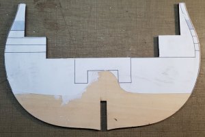
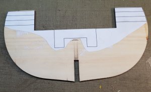
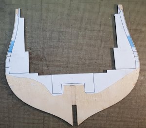
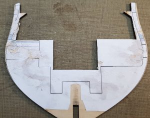
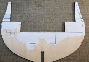
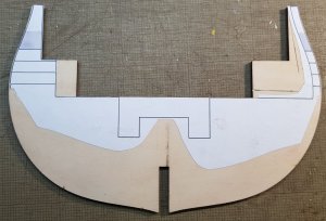
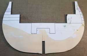
The next series of photos are the reverse side of first 11 bulkheads.
These drawings, that has been placed on the bulkheads are alterations for each them so that my overall visualisation will hopefully come to a full fruition. These drawing will be the guide for cutting, which I'll be doing very soon.

20180324_020447.jpg
Bulkhead 1

20180324_015234.jpg
Bulkhead 2

20180324_015318.jpg
Bulkhead 3

20180324_015903.jpg
Bulkhead 4

20180324_015934.jpg
Bulkhead 5

20180324_015959.jpg
Bulkhead 6

20180324_020202.jpg
Bulkhead 7

20180324_020302.jpg
Bulkhead 8

20180324_020231.jpg
Bulkhead 9

20180324_020342.jpg
Bulkhead 10


20180324_020416.jpg
Bulkhead 11

To make my life easier, I have drawn the the positions of the Wales, the area where the chain plates are and the support for the deckings.
Yes, I have taken into account of the 7 mm of the thickness bulkheads. So these lines should be accurate.
You might think to yourself, why put these lines on?
Simple.......The Wales will be placed directly on the bulkheads because there a is only going to be one layer of planking. I'm not going to do the double planking method of the kits because of the opening on the starboard side. The upper sides of hull planking will be added after a period of time. Doing this, I will have more control of the placement of the chain plates.
You may also be wondering, why some the bulkheads are not symmetrical. Bulkheads 2 to 6 are designed to let me show the crews quartets. More of this will be discuss in future logs.
;)
Personally I'm am so pleased to finally to have a start on this increadale kit. It was a hard slog doing these alterations and you will see more of my drawings in the next log.
Thanks for watching and happymodeling to all
Greg
 
Hi greg, good to see it is dust time.
I think you already deserve a reward for starting to create dust and already have 6 pages in your blog.
I love your blog with all your thoughts and well layed out approuch to this build. I will be sitting front row, if there is still a spot free, for your great conversion of this kit. Lots of fun.

Regs Maarten

Thank you Maarten for your kinds words. My last two logs doesn't show very much of the saw dust, but believe me, I have a half full very large garbage bag in the garage with all the saw dust up till now.
My next log is where the saw dust will be scattered.
:p
Havagooday and happymodeling mate
Greg
 
...My last two logs doesn't show very much of the saw dust, but believe me, I have a half full very large garbage bag in the garage with all the saw dust up till now....
:eek: Where did all the wood come from to build this kit? :D:D:D

I'll be watching this sawdust phenomenon ;)

fEYx3xi.gif
 
Back
Top