weeeee had fun yesterday head cold kicking in full throttle called dr office nurse said any cold med was fine so took dayquil extreme cold and flu and man i was higher than a kite I was up on cloud 9 lol talked to pharmacist and she said yes i could but i should do one without a decongetant ans that will do that too me so i got some Coricidin HBP made for peeps with high blood pressure. im feeling a wee bit better but i need to try to find something to break up all this phlem so I feel like even doing something lol work killing me but I used all my time off time til jan
You are using an out of date browser. It may not display this or other websites correctly.
You should upgrade or use an alternative browser.
You should upgrade or use an alternative browser.
G'day Joseph
Hope that the crappie fealing soon disappears and you're back to normal.
Getwellsoon
Greg
Hope that the crappie fealing soon disappears and you're back to normal.
Getwellsoon
Greg
thanks its worse cause i cant take the good stuff due to old fart pills usually i can kill it in 24 hrs its been 4 days now
Last edited:
Ok I am through Most of this Cold/Flu bug and off today, so going to try and do some work as well as still get my rest.
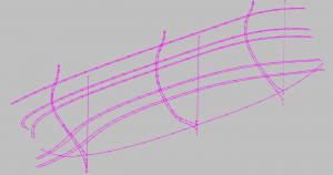
It is going to be a very very slow process right now as I am trying to get the interior lofted and I want to make sure to get a smooth flow and not overly thick frames in spots. To do this I will have to measure and place placeholders at each waterline for every frame to acheive this. That in itself will take several hours to set up then I should be able to get it done.
It is going to be a very very slow process right now as I am trying to get the interior lofted and I want to make sure to get a smooth flow and not overly thick frames in spots. To do this I will have to measure and place placeholders at each waterline for every frame to acheive this. That in itself will take several hours to set up then I should be able to get it done.
Ok so I got a good portion of the hull lofted. there are a few areas still on the front and rear I need to work on but you can see from the zebra stripes on the part I been working how nice and smooth they are. so far so good at least visually. once i get each individual station there may be problem areas.
If I actually knew how to properly draw the inner section for each frame it would make this a whole lot easier I could then loft after that to double check.
I had found a few ways that were ok before but they always ended up with errors later. So I need to research how they come up with the inner lines. The outer is always shown in tutorials but not how to PROPERLY do the interiors just tricks to get them close.
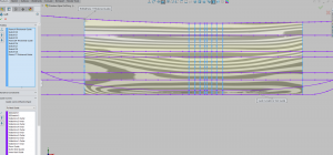

Ok after spending tons of time working on this there is numerous errors once I sliced the loft apart so it is back to the starting board starting from scratch and this time just work small sections at a time and build from there. Probably doesnt help I been away from it for a while so probably forgetting some simple things. However I have Ed Tostis Naiaid books that really get down on computer cadding to read up on and jog my memory
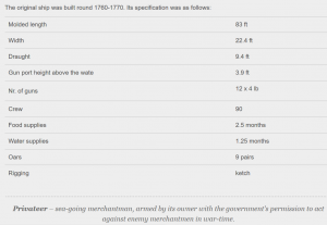
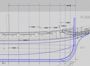
Soo I think since I need to start over I want to go simple small but elegant and the ship I want to do is the one in the image I posted at the start as it is a nice little ketch and 12 gun privateer type. I know that its from Chapman's plate 39 vessel nr. 1 however on chapmans virtual museum I have a pain trying to figure my way around as I dont speak sweedish and translater doesnt really work that great.
https://digitaltmuseum.se/search/?q=Chapman,Fredrik,Henrik,af,ritningar&o=0&n=128
so I am going through everything and the web trying to find a decent high res image of the drawings. Since I have this thread with drawing info on it pre request I will continue this thread.
Anyone can help me out here be appreciated
Also shown was this reference to it "Fredrik Chapman (the album «"Architectura navalis mercatoria", page ХХХIХ drawing 9). "
Last edited:
Ok so tonight I will get re-started so here we go and Greg since you asked before I will continute how I do it and now since I got my new drawings and starting from scratch I can show the ENTIRE process.
as soon as I get my new setup going I will post a couple images of my folders so you can see how I organize my file folders too to make things easier
as soon as I get my new setup going I will post a couple images of my folders so you can see how I organize my file folders too to make things easier
So the first thing I do of course is make a folder for my project. I then create several sub folders. these I show are basics and more added as needed.
So the first image I show my basic working folder where I try to separate everything to make it easy to find materials I need
The scond image is of my Solidworks folder. Since you will have tons of part files and assemblies. I try to think of how I will do it in my program. each major assembly in my program I try to make a folder for. inside of each folder for example the Stations folder I will have sub folder for each station for example DF-01 F will have its own and then DF-01 A will have its own. this will make it easier when editing a part or finding one for printing etc. depending on the type ship and the way you are framing ie using chocks, it can have up to 9 part files for each station possibly more. so over 50 frames that would be a lot of parts just to dump into 1 folder.
and that's how i do a basic setup[ for my work folder which I can then add more folders etc as needed

So the next thing I do is to open Solidworks and create a new part file that I called Privateer Layout Files. I use this for my tracings and other work drawings that I will use during the entire process.
I then take and draw out my Perpendiculars and my top of keel and dimension it between the perpendiculars so I have something as a reference for enlarging my image for tracing. I also draw all my ships at full scale as then if someone asks me for a scale I am not doing it is easy just to rescale it.
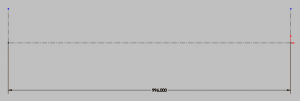
I then take and draw out my Perpendiculars and my top of keel and dimension it between the perpendiculars so I have something as a reference for enlarging my image for tracing. I also draw all my ships at full scale as then if someone asks me for a scale I am not doing it is easy just to rescale it.

so now I have my image imported and scaled properly.
As you can see the images lines are dark and will make it a little more difficult when tracing. You can trace like this but it is a pain. I also have the image on a seperate sketch layer than everything else so that I can turn visibility on and off at will.
So fortunately in Solidworks I can adjust the transparency of the image. I find that 60% is abt right some images may need less or more depending on the darkness of your lines.
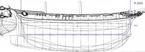
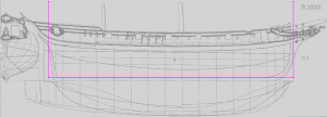


Next I like to take a minute and draw a few chicken scratch lines to see how my other drawings look. the one thing stood out immediatly before I even began is to look at the top of the keel and how the body plan lines up. it is way off
As you can see here from these 2 images I was right, the body plan is way off. my next will be to measure the width and see if that's close or not.
Once I know roughly where the errors are I will trace everything as is and when finished line everything up again and start adjusting as necessary.
Usually when you see me drawing I try to have all that done and just start showing me starting my drawings. Since this is also a how I do it thread I have included these steps. Next I will also goto my reference books and try to find a ship close to the same size to use for reference dimensions.
I think a sloop is a little bigger than this ship but might be close enough. I did find info for a 10 gun Denmark Yacht and this is a 12 gun Yacht so I think this sb the correct info for this ship as close as can get. I will check the scantlings to check the length between the perps
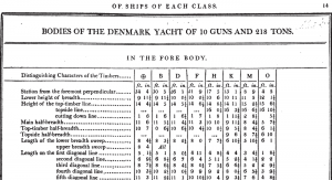

So Looking into the scantlings it says 89.5' So I think to make this work and make life easier I will adjust the perpendiculars and drawings to match the scantlings. it is only like a 6 ft difference so wont be noticeable.
So Now I will start tracing. The First thing I like to do is to find the depth of the keel, false keel, and the Rabbet. When I start I try to get the Profile plan as corrected as possible as I go since it is usually just a series of fairly straight lines. it is the waterline and body plans I do as is.
So in this case the Keel is 13" 3 Pieces, Rabbet 2 3/4", False Keel 4" and 4 Pieces
So in this case the Keel is 13" 3 Pieces, Rabbet 2 3/4", False Keel 4" and 4 Pieces
So Now I have the basic Keel and Bow area drawn up. I used arcs and lines to be sure everything was fluid then compied them with splines and did some tricks so that now I have long solid lines which makes things easier later on because I wont have tons of nodes etc in the background. Basically I just cleaned up my drawings using tricks I learned just to make things visually easier to read. it doesn't change the drawings any other way.
I also made them overly long so that I can use them for layout of other stuff later and for guides when lofting. I will also make a copy of the sketch and trim them for my normal drawings. I often do several of the same drawings so I can use them later on without needing to adjust things on the originals.
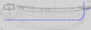
I also made them overly long so that I can use them for layout of other stuff later and for guides when lofting. I will also make a copy of the sketch and trim them for my normal drawings. I often do several of the same drawings so I can use them later on without needing to adjust things on the originals.

So after I finished all that tracing I went back and adjusted everything to the proper dimensions as listed in steels book for the rabbet false keel and keel and started drawing out my Keel and False Keel Parts. I will add station lines and trace the decks etc then start breaking down the Bow and Stern areas into their parts.
This is the work flow I always follow. Once the Profile is finished then I work other stuff. I probably wont post a lot more photos of the Profile as you all know roughly how they are done. I only wanted to get my work flow shown and start showing you how to get into the habbit of looking for and adjusting errors as you go for the profile, as once you have the profile that is to me the most important part of the ship needed to create drawings. Waterlines and stations can be figured out anytime, but the profile is needed to be able to accurately correct those.
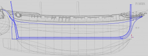
This is the work flow I always follow. Once the Profile is finished then I work other stuff. I probably wont post a lot more photos of the Profile as you all know roughly how they are done. I only wanted to get my work flow shown and start showing you how to get into the habbit of looking for and adjusting errors as you go for the profile, as once you have the profile that is to me the most important part of the ship needed to create drawings. Waterlines and stations can be figured out anytime, but the profile is needed to be able to accurately correct those.


