Constructo 1799 Enterprise help

Modeling Paste:

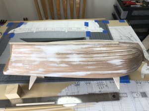
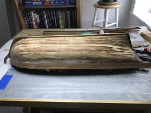
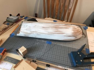
I applied the modeling paste to one side of the hull. The paste is thick/stiff?

The paste does sand easily. It does a great job filling in some of the voids.
576E9B97-D54C-46AC-9771-86DB9DD412C1.jpeg

It does require a lot of sanding. I could not brush on an even coat. I’ve not done enough research to see if the paste can be thinned out.

(Edit: I found out the paste can be thinned with a small amount of water. Again another reason to do the research before doing the work)
 
Last edited:
Mike, Donnie,

My little nook is a great place to do model work.

Currently I’m sanding, vacuuming, sanding, vacuuming, sanding .........

I’m trying very hard to not upset the local real estate manager because it’s very cold outside this time of year.
 
Hi Mr. Pathfinder,
That's why I love Los Vegas. Yesterday it was 77Deg F. Today was 73 F. Great looking build and I like your log easy to follow.
 
Modeling Paste part 2:

I think I over pasted in part one. But after several hours of sanding with coarse, medium and fine sandpaper the result looks good.

39BBB25D-F450-484F-B4F4-8AC372F830C4.jpeg
 
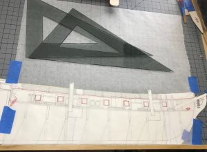
Gun port template.

I started out tracing the gun ports from a side view template that I have been using as a reference. I thought that wax paper would be great to use to trace the gun ports. BUT I found that using a fine Sharpi or a 2H pencil the wax on the wax paper was enough to dull the points of the Sharpi or the pencil.

I ordered a packet of artist tracing paper (14 X 17 in). That came in my favorite FEDEX truck yesterday.

This morning I gave it a try.

C8249637-58BA-47BF-AE82-3C17DC5CCEA2.jpeg

I thought I had solved my problem. I used a fine point Sharpi to trace the gun ports. After tracing the third port I could see that the three that I had completed were not the same size. I found the same problem when I traced the ports from the actual plan. So, the conclusion is the plans are reference and not to scale.

I’ll post a picture of my thoughts and maybe better method to my problem later.
 
  • Like
Reactions: ADC
Odds and ends:

The hull sanding and filling is almost done.

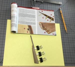
I thought I might work on some of the other parts of the build. The rudder seemed like a good place to start.

A19026EC-1403-49D1-9CE3-3505575F40DB.jpeg

I had made a template earlier and used that as an aid cutting out the areas for the hinge joints. I made a jig for each set of hinges and adjusted the rudder cutouts until the hinges fit.

78820DE3-8E2E-422C-83C1-E226A78A9A42.jpeg
 
Gun ports revisited:

I think I’ve found a method to mark the location of the gun ports.

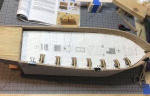
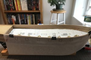
I laid the deck template made earlier on the main deck. A small amount of sticky tape on the bottom of the gun carriage holds the carronades in place. I clipped the tracing of the gun ports to the side of the hull. Looking down at the deck and then looking at the attached tracing, not much adjustment was needed.
The dimensions of the gun ports appear to be 12 X 13mm or 13 X 13mm.


A1BC3B95-AADB-4311-A543-CBD6561420B9.jpeg4AFFADA3-772F-488E-8A67-73C77F72099C.jpeg

I think the next step will be to add the second planking down to the waterline and then cut in gun ports.
 
Another interesting find:

Not having modeled early warships I’m finding that I lack a lot of knowledge about their construction and armament.

I had no idea of the type cannons that were part of and used by different classes of ships.

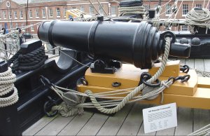
The picture below is the result of a search for carronades. It will be a good reference for my build.

77349BBD-DA48-4E76-8196-261B20307A6E.jpeg
 
Wales:

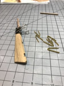
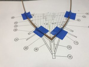
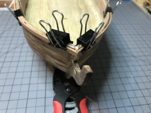
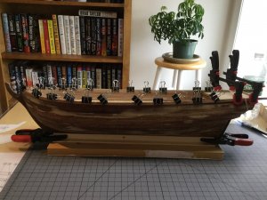
The pieces for the Wales have been drying in my “bending jig”. I temporarily clamped the port and starboard Wales to the top rail. I could not come up with a good method of fitting and cutting them to fit the bow. Once again I copied the top view of the deck plan , pasted that to some card stock, used tape to hold the wale in place and cut the ends of the Wales to the proper shape.

A4A6FA9D-D9BC-4D77-8351-6132F882DF94.jpeg
 
AF420F1F-3910-4CD7-A745-1244A7D90A95.jpeg

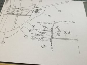
My instructions do not have a section on where to start the 2nd planking. The above plan profile shows the 1st planking (2X6mm), the upper wale, the lower wales, guard rail and the gallant rails.

Does the 2nd planking start in a similar fashion as the 1st? That planking was started 1mm below the deck or does it start below the upper wale.

My thought is to start the 2nd planking in the same way as the 1st planking. I would think that the lower wales would be glued on top of the 2nd planking.

Suggestions are welcome.
 
2nd Planking:

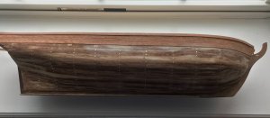
I’ve searched for pictures of the hull for this model. All appear to show the 2nd planking starting at the upper wale. I was going to mark the hull to see how many planks would be needed starting at the upper wale and ending at the keel. But I came up with a better idea.

4CECA83F-B1F8-4554-8182-1371AF0E4C23.jpeg
80AEE21D-CA93-4C1C-A378-8AC471A919BB.jpeg

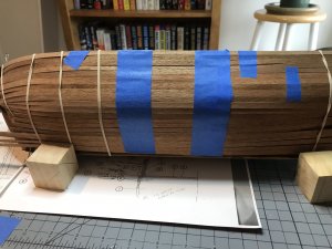
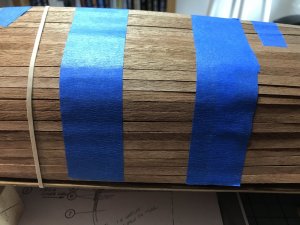
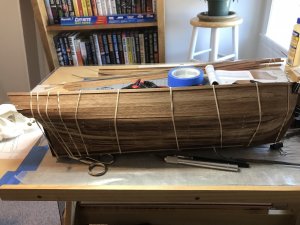
Why not test fit a side and count the number of planks used. It worked out to be 21. There are 55 supplied with the kit. The plan is to start planking at the upper wale to the “waterline” and up from the keel.
 
DDB1EA9D-230E-481E-8BD5-9CA9DB7DDDEE.jpeg

Start of second planking. Not sure of what type of glue to use. Started with Titebond III Ultimate,the “working time” versus Titebond II Premium was about the same. Best result seemed to be Elmer’s High Performance Repair Glue. I also tried Stick Fast CA thin and Stick Fast CA Thick.

995D2CAC-F3AB-4D44-9E66-D51D31607EC8.jpeg

CA3737BB-3172-43CB-88CB-097AB31094BF.jpeg

Current progress is slow. I’m finding that affixing one plank and allowing the glue to “set” is the best method. The planks also have very “rough” edges that need to be lightly sanded to get a good butt up fit.
 
Last edited:
Back
Top